Condenser

A technology for condensers and refrigerants, which is applied to evaporators/condensers, refrigerators, refrigeration components, etc., can solve the problems of reducing the heat dissipation capacity of the condenser, reducing the heat exchange capacity of the condenser, and small refrigerant charging capacity. Improve heat dissipation effect, improve heat transfer effect, improve heat transfer surface area effect

Pending Publication Date: 2017-02-08
SHENZHEN SHANYUAN ELECTRONICS
View PDF9 Cites 0 Cited by
  • Summary
  • Abstract
  • Description
  • Claims
  • Application Information

AI Technical Summary

Problems solved by technology

[0003] At present, the commonly used condensers are tube-strip condensers and parallel flow condensers, but the tube-strip condensers are composed of copper tubes and aluminum sheets, the cost is relatively high, the processing technology is complicated, and the most important thing is the copper tube and aluminum sheet. The contact thermal resistance between them is relatively large, which reduces the heat dissipation capacity of the condenser; the parallel flow condenser is composed of a collecting tube, flat tubes and louver fins, and is made of aluminum, and the net area ratio of the flat tubes in the direction of air flow is greater than Ordinary round tubes reduce the flow resistance of air. Compared with the tube-belt condenser, it reduces the production cost, the refrigerant charge is small, the structure is compact, and the heat exchange capacity is high; but the channel form of the parallel flow condenser is single, As a result, the temperature of the refrigerant pipe outlet of each condenser pipe varies greatly, resulting in uneven heat transfer and reducing the heat transfer capacity of the overall condenser

Method used


Image

  • Condenser
  • Condenser

Examples


Embodiment Construction

[0042] It should be noted that, in the case of no conflict, the embodiments of the present invention and the features in the embodiments can be combined with each other.

[0043] In describing the present invention, it should be understood that the terms "center", "longitudinal", "transverse", "upper", "lower", "front", "rear", "left", "right", The orientations or positional relationships indicated by "vertical", "horizontal", "top", "bottom", "inner", "outer", etc. are based on the orientation or positional relationships shown in the drawings, and are only for the convenience of describing the present invention Creation and simplification of description, rather than indicating or implying that the device or element referred to must have a specific orientation, be constructed and operate in a specific orientation, and therefore should not be construed as limiting the invention. In addition, the terms "first", "second", etc. are used for descriptive purposes only, and should no...


PUM


Abstract

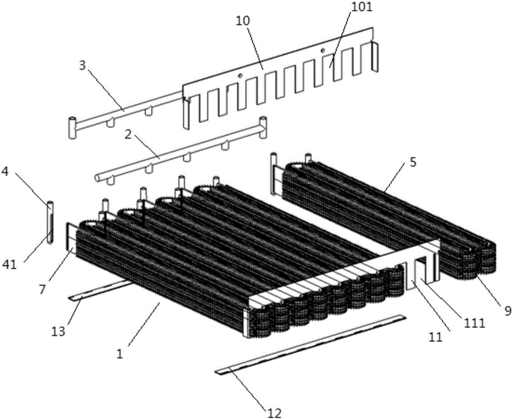
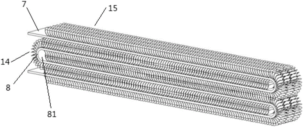
The invention provides a condenser which comprises a first refrigerating pipeline assembly; the first refrigerating pipeline assembly comprises a refrigerating pipeline which is formed by bending once; a bent position of the refrigerating pipeline is a bent section of the refrigerating pipeline, the other parts of the refrigerating pipeline are basal plate sections, and the end parts of every two adjacent base plate sections are connected through the bent sections; a plurality of rows of fin groups which are parallel to one other are arranged on the upper end surface and the lower end surface of each base plate section; each row of fin groups consists of a plurality of fins which are parallel to one other; the fins of the adjacent two rows of fin groups are arranged in a spaced manner and are parallel to one another; a plurality of rows of rib fin groups which are parallel to one another are arranged on the outer end surface of each bent section; each row of rib fin groups consist of a group of rib fins which are parallel to one another; and the rib fins of adjacent two rows of rib fin groups are arranged in the spaced manner and are parallel to one another. The condenser increases air turbulent flow and increases a heat radiating area, further improves heat radiating effect, and further improves whole heat exchange effect.

Description

technical field [0001] The invention belongs to the field of condensation equipment, and in particular relates to a condenser. Background technique [0002] In recent years, due to the increasing popularity of air conditioners, most household air conditioner condensers use finned tube air-cooled condensers. The refrigerant flows in the tube to release heat, and the air flows between the fins outside the tube and absorbs the heat released by the refrigerant. , Through the cold and heat exchange between the refrigerant and the air, summer cooling is realized. [0003] At present, the commonly used condensers are tube-strip condensers and parallel flow condensers, but the tube-strip condensers are composed of copper tubes and aluminum sheets, the cost is relatively high, the processing technology is complicated, and the most important thing is the copper tube and aluminum sheet. The contact thermal resistance between them is relatively large, which reduces the heat dissipation...

Claims


Application Information

Patent Timeline
Patent Type & Authority Applications(China)
IPC IPC(8): F25B39/04
CPCF25B39/04
Inventor 刘士群张广全李洪坤张金广刘征
Owner SHENZHEN SHANYUAN ELECTRONICS
Why Eureka
Try Eureka