Current control system and method for grid-connected converter of DC micro-grid

A DC micro-grid and control system technology, applied in the direction of converting AC power input to DC power output, electrical components, single-net parallel feeding arrangement, etc., can solve problems such as bidirectional flow of power that cannot be realized, line impedance, etc.

Inactive Publication Date: 2018-09-07
XIAN UNIV OF TECH
View PDF4 Cites 12 Cited by
  • Summary
  • Abstract
  • Description
  • Claims
  • Application Information

AI Technical Summary

Problems solved by technology

[0004] The purpose of the present invention is to provide a control system for the current of the DC microgrid grid-connected converter, which solves the problem that the control of the grid-connected converter in the DC microgrid in the prior art cannot realize the bidirectional flow of power and there is line impedance

Method used


Image

  • Current control system and method for grid-connected converter of DC micro-grid
  • Current control system and method for grid-connected converter of DC micro-grid
  • Current control system and method for grid-connected converter of DC micro-grid

Examples


Embodiment Construction

[0066] The present invention will be described in detail below in conjunction with the accompanying drawings and specific embodiments.

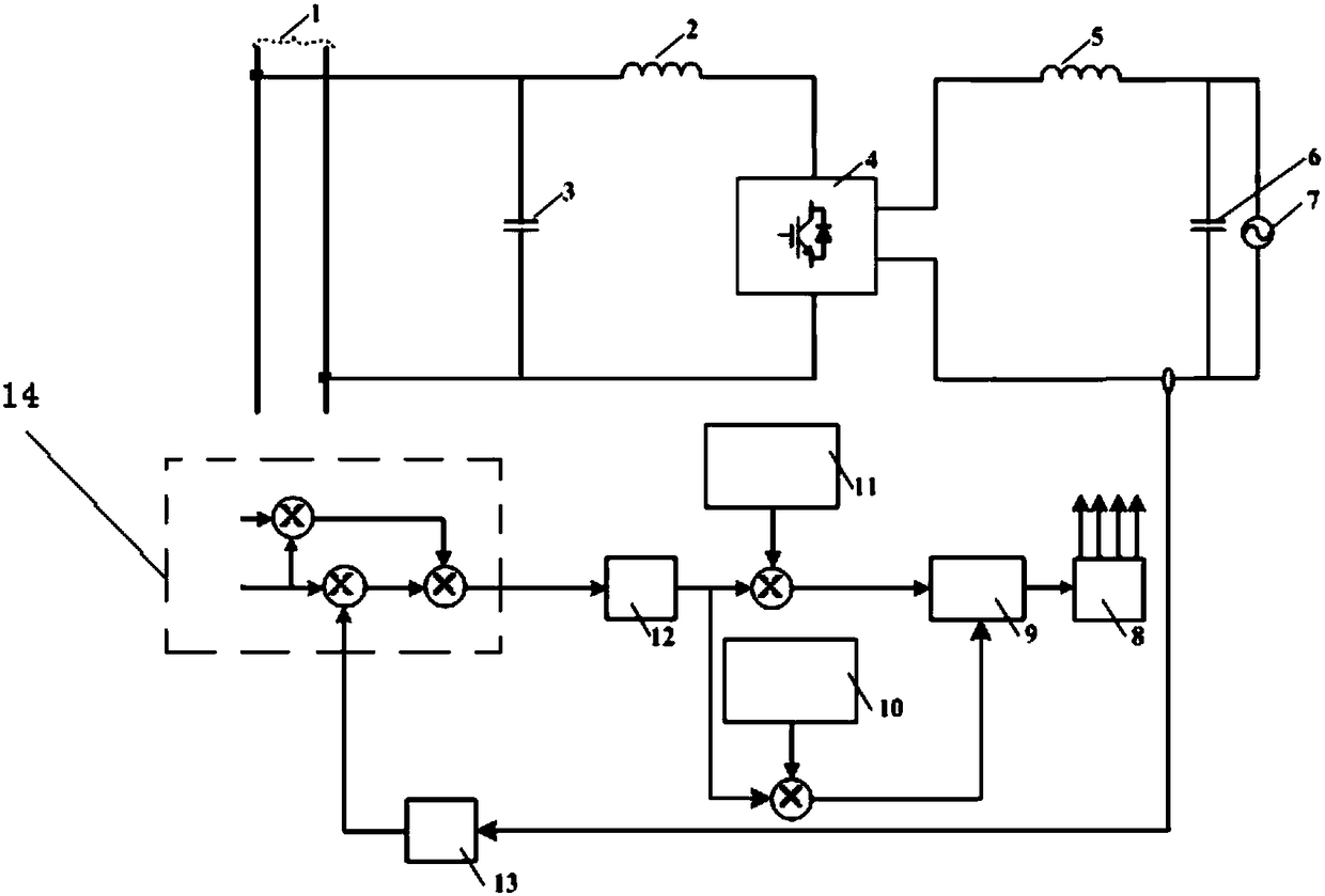
[0067] The present invention is a control system for the current of a DC micro-grid grid-connected converter, such as figure 1 As shown, it consists of a bidirectional converter topology circuit and a control circuit, wherein the specific structure of the bidirectional converter topology circuit is: a single-phase converter 4 is included, and the DC side of the single-phase converter 4 is sequentially connected to a current-limiting inductor L S 2 and DC bus DC BUS 1, current limiting inductor L S A stabilizing capacitor C is also connected between 2 and the DC bus DC BUS 1 O One end of 3, the voltage stabilizing capacitor C O The other end of 3 is connected to the other DC side of the single-phase converter 4, and the AC side of the single-phase converter 4 is sequentially connected to a filter inductor L S 5 and filter capacitor C ...


PUM


Abstract

The invention discloses a current control system and method for the grid-connected converter of a DC micro-grid. The method comprises pre-estimating the power of the grid-connected converter by the change of DC bus voltage; calculating the steady-state value of the inductive current according to the change of the DC bus voltage; and establishing a linear control relationship between the DC bus voltage and the inductive current to predict directive current. The control strategy improves the current control accuracy of the grid-connected converter, increases response speed, and improves the dynamic and static performance of the grid-side current of the grid-connected converter, reduces the influence of system parameter changes on the grid-side current, and enhances the robustness of the DC micro-grid. The DC micro-grid grid-connected converter current control strategy and device include a bidirectional converter topology circuit and its control device, and solve the problem that the control of the grid-connected converter in the DC micro-grid in the prior art cannot realize bidirectional power flow and the grid-connected converter has line impedance.

Description

technical field [0001] The invention belongs to the technical field of new energy power generation and electric energy conversion, and in particular relates to a control system for the current of a DC microgrid grid-connected converter, and the invention also relates to a control method for the current of the DC microgrid grid-connected converter. Background technique [0002] In recent years, with the reduction of fossil energy, the destruction of the earth's environment, and the increasing demand for electric energy, renewable energy has been widely used. As an important part of the future smart distribution network, the DC microgrid can more efficiently and reliably receive distributed renewable energy generation systems such as wind and light, energy storage units, electric vehicles, etc., and needs to be connected through grid-connected inverters distribution network. The grid-connected converter in the DC microgrid can realize the power conversion and the bidirectiona...

Claims


Application Information

Patent Timeline
Patent Type & Authority Applications(China)
IPC IPC(8): H02M7/797H02J3/38
CPCH02J3/38H02M7/797
Inventor 支娜闫海明张辉李宁张伟亮
Owner XIAN UNIV OF TECH
Why Eureka
Try Eureka