
Broadband phase-locked frequency source equipment

A frequency source and phase locking technology, applied in the field of frequency sources, can solve the problems of low output frequency, high phase noise and high cost, and achieve the effect of reducing cost and improving phase noise.

Pending Publication Date: 2018-09-07
36TH RES INST OF CETC
View PDF7 Cites 3 Cited by
  • Summary
  • Abstract
  • Description
  • Claims
  • Application Information

AI Technical Summary

Problems solved by technology

[0004] In view of the above analysis, the present invention aims to provide a harmonic diode mixing circuit and a broadband phase-locked frequency source device to solve the problems of high phase noise, low output frequency and high cost in the prior art

Method used


Image

  • Broadband phase-locked frequency source equipment
  • Broadband phase-locked frequency source equipment
  • Broadband phase-locked frequency source equipment

Examples


Embodiment 1

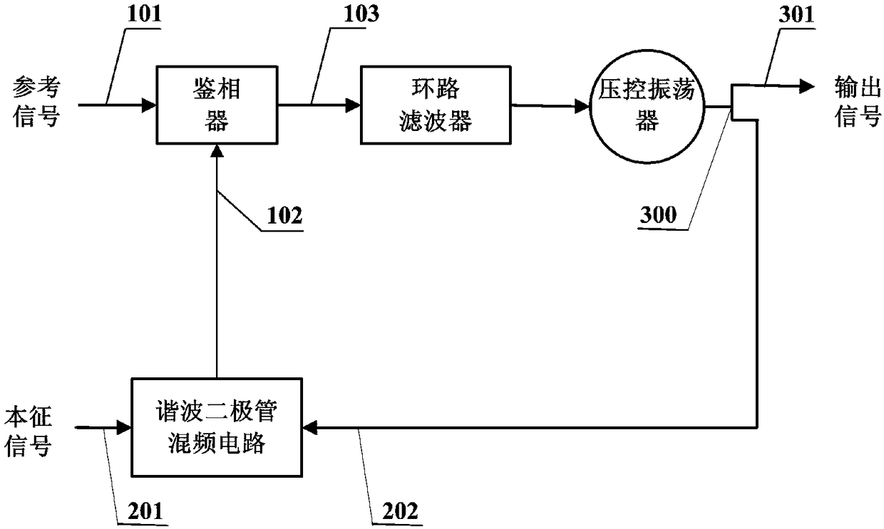
[0051] A specific embodiment of the present invention discloses a broadband phase-locked frequency source device, such as figure 1 shown. The broadband phase-locked frequency source device includes a forward path and a feedback path. The forward path includes a phase detector, loop filter, and voltage-controlled oscillator; the feedback path includes a harmonic diode mixer circuit. The forward path and the feedback path together form a phase-locked loop.

[0052] The phase-locked loop has excellent characteristics, it has carrier tracking characteristics, can be used as a frequency source to provide a series of high-frequency stable frequency signals, and can also perform high-precision phase and frequency measurements. Theoretically, the phase-locked loop can generate an electrical signal with any frequency and high precision.

[0053] The phase detector includes a reference signal input terminal, a feedback input terminal and an output terminal. The reference signal inp...

Embodiment 2

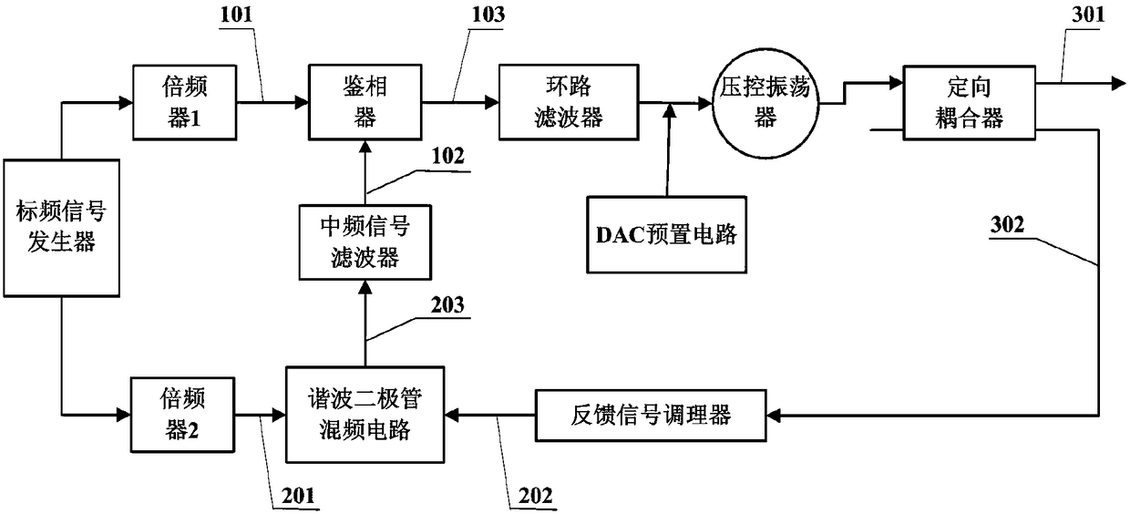
[0069] Such as figure 2 As shown, optimized on the basis of the above-mentioned embodiments, the broadband phase-locked frequency source device may further include a standard frequency signal generator and two frequency multipliers (ie, frequency multiplier 1 and frequency multiplier 2). The standard frequency signal generator includes two output terminals, which are respectively connected to the frequency multiplier 1 and the frequency multiplier 2 .

[0070] Optionally, the standard frequency signal generator includes an oven-controlled crystal oscillator (OCXO) and required power division and coupling circuits. The standard frequency signal generator is used to generate two channels of standard frequency signals.

[0071] The frequency multiplier 1 and the frequency multiplier 2 include a frequency multiplication element or a frequency multiplication circuit and a corresponding filtering and amplifying circuit. The frequency multiplier 1 and the frequency multiplier 2 re...


PUM


Abstract

The invention relates to broadband phase-locked frequency source equipment, belongs to the frequency source technology field, and is used to solve the problems of the prior art such as high phase noises, low output frequency, and high costs. The broadband phase-locked frequency source equipment comprises a forward path and a feedback path. The forward path comprises a phase discriminator, a loop filter, and a voltage-controlled oscillator. The feedback path comprises a harmonic diode mixing circuit. After the phase-locked loop is locked, the broadband phase-locked frequency source equipment isused to output a stable frequency signal, and is used for down conversion of a radio frequency signal to a relatively low medium frequency signal to improve a frequency synthesizer phase noise. The harmonic diode mixing circuit adopts even order harmonics of a local oscillation signal and the radio frequency signal for mixing, and when the output frequency is high, a large frequency doubling device is not required to be additionally disposed on a local oscillation input end, and therefore costs are saved. The equipment has advantages of simple operation, strong universality, low production costs, and strong applicability.

Description

technical field [0001] The invention relates to the technical field of frequency sources, in particular to a broadband phase-locked frequency source device. Background technique [0002] As an important part of the modern electronic communication field, the phase-locked frequency source is widely used in various electronic devices such as receiver systems, radar systems, and electronic test and measurement systems to provide a stable and high-quality frequency signal for these devices . With the continuous development of electronic technology, the equipment system puts forward higher requirements on the phase noise index of the frequency source. The broadband phase-locked frequency source based on harmonic diode mixing achieves the purpose of reducing the output phase noise by reducing the loop frequency division ratio. [0003] For the phase-locked frequency source of the general feedback loop interpolation mixer, the fundamental wave of the frequency multiplier is usuall...

Claims


Application Information

Patent Timeline
IPC IPC(8): H03L7/085H03L7/18
CPCH03L7/085H03L7/18
Inventor 钱焕裕周叶华叶宝盛
Owner 36TH RES INST OF CETC
Learn More