Efficient stamping device for processing back shell of motor and application method thereof
A technology of stamping device and rear shell, applied in the field of stamping device, can solve the problems of troublesome maintenance and high cost of using a mechanical arm, and achieve the effects of reducing power equipment, improving stamping efficiency and ensuring stability
- Summary
- Abstract
- Description
- Claims
- Application Information
AI Technical Summary
Problems solved by technology
Method used
Image
Examples
Embodiment 1
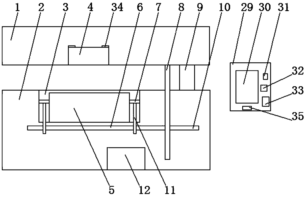
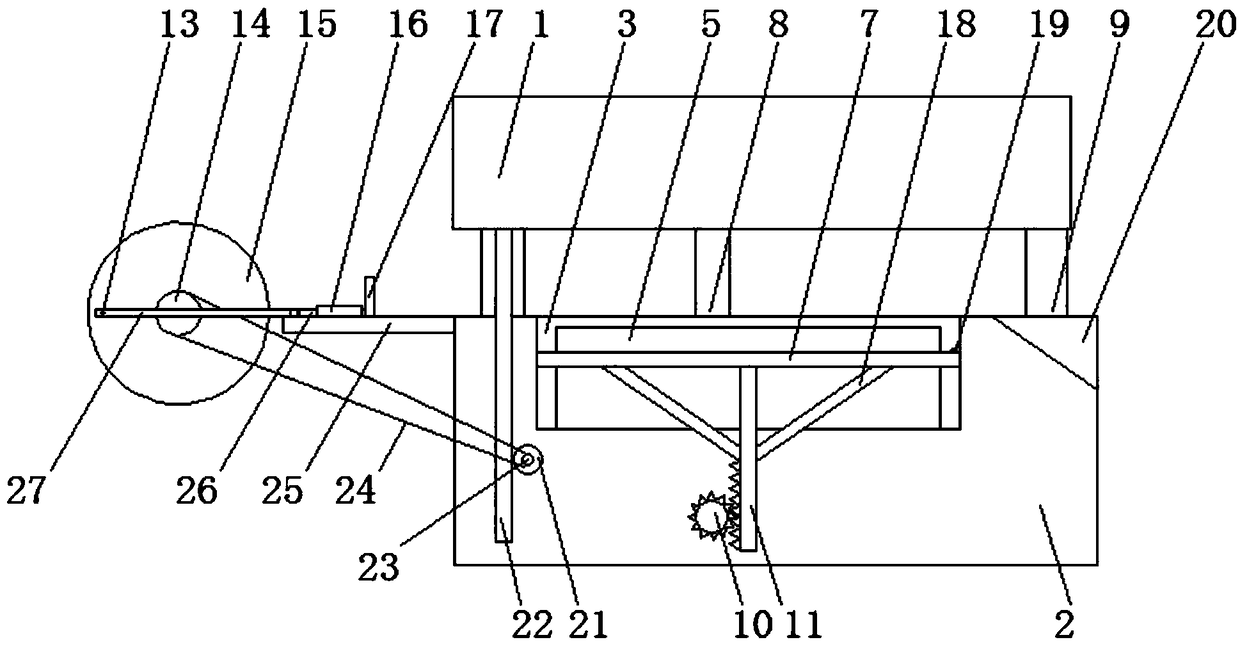
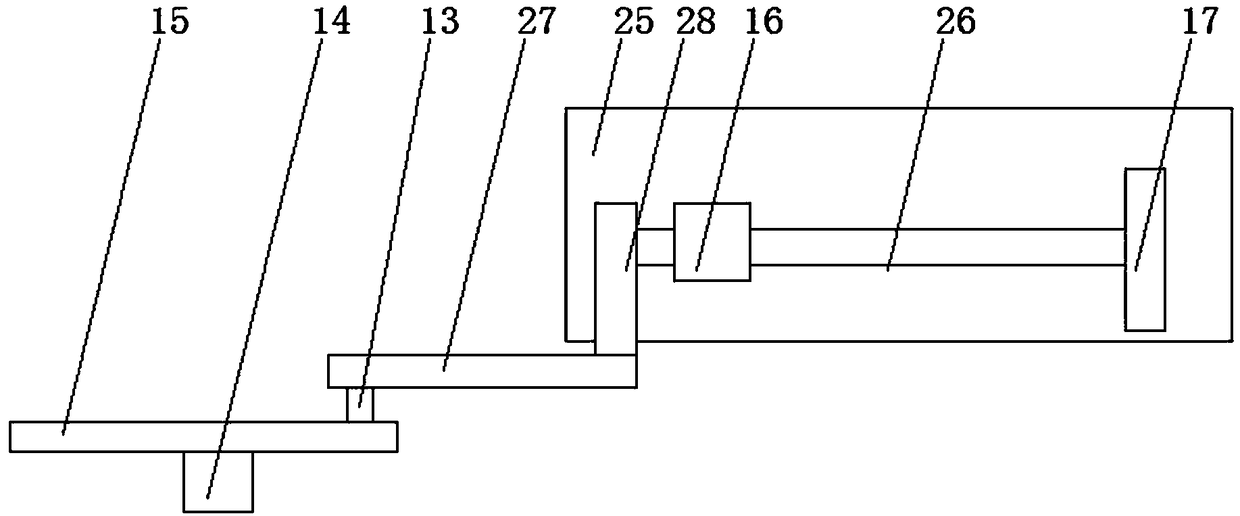
[0027] Embodiment 1, a stamping device for a high-efficiency motor shell equipped with a pressure induction tester, including a stamping base 2, a stamping groove 3 is provided in the middle of the stamping base 2, and a stamping die 5 is provided in the stamping groove 3, so that A top plate 7 is provided between both sides of the stamping die 5 and the stamping groove 3, the bottom of the top plate 7 is provided with a first fixed lever 11, and the bottom of the first fixed lever 11 is connected to the first rotating shaft 10 through gear engagement. , the upper end of the stamping base 2 is connected to the stamping cover plate 1 through a number of evenly distributed hydraulic rods 9, the middle part of the bottom of the stamping cover plate 1 is provided with a punching machine 4 matching the stamping die 5, and the stamping cover plate 1 One side of the bottom is provided with a fixedly connected first gear bar 8, the bottom of the first gear bar 8 is connected to the fir...
Embodiment 2
[0032]Embodiment 2, a stamping device for a high-efficiency motor shell equipped with a pressure induction tester, including a stamping base 2, a stamping groove 3 is provided in the middle of the stamping base 2, and a stamping die 5 is provided in the stamping groove 3, so that A top plate 7 is provided between both sides of the stamping die 5 and the stamping groove 3, the bottom of the top plate 7 is provided with a first fixed lever 11, and the bottom of the first fixed lever 11 is connected to the first rotating shaft 10 through gear engagement. , the upper end of the stamping base 2 is connected to the stamping cover plate 1 through a number of evenly distributed hydraulic rods 9, the middle part of the bottom of the stamping cover plate 1 is provided with a punching machine 4 matching the stamping die 5, and the stamping cover plate 1 One side of the bottom is provided with a fixedly connected first gear bar 8, the bottom of the first gear bar 8 is connected to the firs...
Embodiment 3
[0037] Embodiment 3, a stamping device for a high-efficiency motor shell equipped with a pressure induction tester, including a stamping base 2, a stamping groove 3 is provided in the middle of the stamping base 2, and a stamping die 5 is provided in the stamping groove 3, so that A top plate 7 is provided between both sides of the stamping die 5 and the stamping groove 3, the bottom of the top plate 7 is provided with a first fixed lever 11, and the bottom of the first fixed lever 11 is connected to the first rotating shaft 10 through gear engagement. , the upper end of the stamping base 2 is connected to the stamping cover plate 1 through a number of evenly distributed hydraulic rods 9, the middle part of the bottom of the stamping cover plate 1 is provided with a punching machine 4 matching the stamping die 5, and the stamping cover plate 1 One side of the bottom is provided with a fixedly connected first gear bar 8, the bottom of the first gear bar 8 is connected to the fir...
PUM
 Abstract
Description
Claims
Application Information
 - R&D
- Intellectual Property
- Life Sciences
- Materials
- Tech Scout
- Unparalleled Data Quality
- Higher Quality Content
- 60% Fewer Hallucinations
Browse by: Latest US Patents, China's latest patents, Technical Efficacy Thesaurus, Application Domain, Technology Topic, Popular Technical Reports.
© 2025 PatSnap. All rights reserved.Legal|Privacy policy|Modern Slavery Act Transparency Statement|Sitemap|About US| Contact US: help@patsnap.com


