A motor slot wedge clamp

A motor slot wedge and fixture technology, which is used in clamping, manufacturing tools, metal processing mechanical parts, etc., can solve problems such as the danger of the unit affecting the overall efficiency of the motor, the impact of rotor dynamic balance, and low assembly efficiency.

Active Publication Date: 2020-10-23
SHANDONG QILU ELECTRIC MOTOR MFG
View PDF6 Cites 0 Cited by
  • Summary
  • Abstract
  • Description
  • Claims
  • Application Information

AI Technical Summary

Problems solved by technology

[0002] At present, in generator manufacturing enterprises, QF series generator rotor wedges are generally clamped on a milling machine or planer by a single piece of vise. This clamping structure has the following disadvantages: 1. It is impossible to clamp two pieces or more at one time. low assembly efficiency; 2. Every time the slot wedge is clamped, it is necessary to ensure that the thickness of the processed slot wedge is consistent, which increases the workload and cost of assembly
Since the inconsistency of the thickness of the rotor slot wedge affects the unevenness of the rotor body, it will inevitably affect the dynamic balance of the rotor, which obviously affects the improvement of the overall efficiency of the motor and the danger of the unit caused by the rotor heating.

Method used


Image

  • A motor slot wedge clamp
  • A motor slot wedge clamp
  • A motor slot wedge clamp

Examples


Embodiment Construction

[0027] In order to clearly illustrate the technical features of this solution, the present invention will be described in detail below through specific implementation modes and in conjunction with the accompanying drawings.

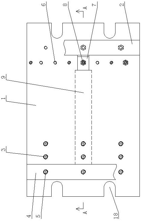
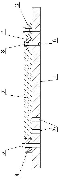
[0028] Such as Figure 1 to Figure 6 As shown, the present invention includes a tire plate 1, a fixed baffle 2 is provided on one side of the upper surface of the tire plate 1, the fixed baffle 2 is arranged along the width direction of the tire plate 1, the fixed baffle 2 is connected with the tire plate 1 through bolts, and the tire plate 1 The other side of the upper surface is provided with three rows of bolt hole groups along its length direction, and each row of bolt hole groups includes three first floor plate bolt holes 3 arranged at intervals along the width direction of the floor plate. The upper surface of the tire plate 1 is provided with an adjustable baffle plate 4, and the adjustable baffle plate 4 is provided with an adjustable baffle plat...


PUM


Abstract

The invention relates to a motor slot wedge clamp. The motor slot wedge clamp comprises a mould plate. A fixed baffle is arranged on one side of the upper surface of the mould plate in the width direction of the mould plate, a plurality of columns of bolt hole sets are formed in the other side of the upper surface of the mould plate in the length direction of the mould plate, and each column of bolt hole set comprises first mould plate bolt holes formed at intervals in the width direction of the mould plate; an adjustable baffle is arranged on the upper surface of the mould plate and connectedwith the first mould plate bolt holes through first bolts penetrating through adjustable baffle bolt holes; a plurality of second mould plate bolt holes are formed in the position, on the inner sideof the fixed baffle, of the upper surface of the mould plate at intervals in the width direction of the mould plate; and a top plate is arranged on the upper surface of the mould plate, is in an L shape and is connected with the second mould plate bolt holes through second bolts penetrating through top plate bolt holes, and the free end of the short edge of the top plate is connected with the fixed baffle in an abutting mode. The motor slot wedge clamp can clamp a plurality of slot wedges at a time, so that the assembling efficiency is improved, the thickness of the machined slot wedges can beensured, and assembling workload and cost are reduced.

Description

technical field [0001] The invention relates to a motor slot wedge clamp. Background technique [0002] At present, in generator manufacturing enterprises, QF series generator rotor wedges are generally clamped on a milling machine or planer by a single piece of vise. This clamping structure has the following disadvantages: 1. It is impossible to clamp two pieces or more at one time. The slot wedge is low in assembly efficiency; 2. Every time the slot wedge is clamped, it is necessary to ensure that the thickness of the processed slot wedge is consistent, which increases the workload and cost of assembly. Since the inconsistency of the thickness of the rotor slot wedge affects the unevenness of the rotor body, it will inevitably affect the dynamic balance of the rotor, which obviously affects the improvement of the overall efficiency of the motor and the danger of the unit caused by the rotor heating. Contents of the invention [0003] The invention provides a slot wedge ...

Claims


Application Information

Patent Timeline
Patent Type & Authority Patents(China)
IPC IPC(8): B23Q3/06
CPCB23Q3/061B23Q3/062
Inventor 刘维峰吕佳李兴隆
Owner SHANDONG QILU ELECTRIC MOTOR MFG
Why Eureka
Try Eureka