Supercharge Your Innovation With Domain-Expert AI Agents!

Liquid crystal display module damping device

A technology of liquid crystal display module and shock absorbing device, which is applied in the directions of transportation and packaging, packaging of vulnerable items, types of packaged items, etc., which can solve problems such as low reliability, poor shock absorption effect, and device damage, and improve protection , improve the shock absorption effect and avoid the broken effect

Inactive Publication Date: 2018-09-11
江苏聚龙显示科技有限公司
View PDF0 Cites 6 Cited by
  • Summary
  • Abstract
  • Description
  • Claims
  • Application Information

AI Technical Summary

Problems solved by technology

[0002] As we all know, the liquid crystal display module shock absorber is an auxiliary device used to protect the liquid crystal display module during transportation, and it has been widely used in the field of liquid crystal display module processing and transportation; the existing The liquid crystal display module damping device includes a placement box, and a placement cavity is arranged inside the placement box, and multiple sets of vertical boards are arranged at equal intervals in the placement cavity, and both sides of the multiple groups of vertical boards are arranged There is a sponge layer, the top of the storage box is provided with a pick-and-place opening, and a door panel is arranged at the pick-and-place opening, and the left end of the door panel is connected with the top left side of the storage box by a hinge; the existing liquid crystal display module shock absorber uses When the liquid crystal display module is vertically inserted between two adjacent groups of boards, the liquid crystal display module is protected by the sponge layers on both sides of the board; The shock absorption effect in the vertical direction is poor, and the liquid crystal display module is easy to cause damage to the internal components due to the up and down vibration during transportation, resulting in low practicability; and it is inevitable that emergency braking will occur during transportation. The group is easily squeezed and the LCD screen is broken, resulting in low reliability

Method used


Image

  • Liquid crystal display module damping device
  • Liquid crystal display module damping device
  • Liquid crystal display module damping device

Examples


Embodiment Construction

[0017] The specific implementation manners of the present invention will be further described in detail below in conjunction with the accompanying drawings and embodiments. The following examples are used to illustrate the present invention, but are not intended to limit the scope of the present invention.

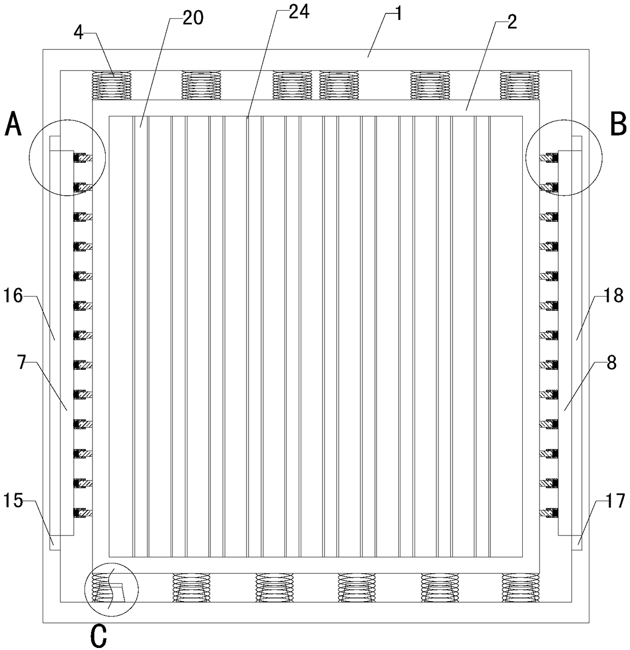
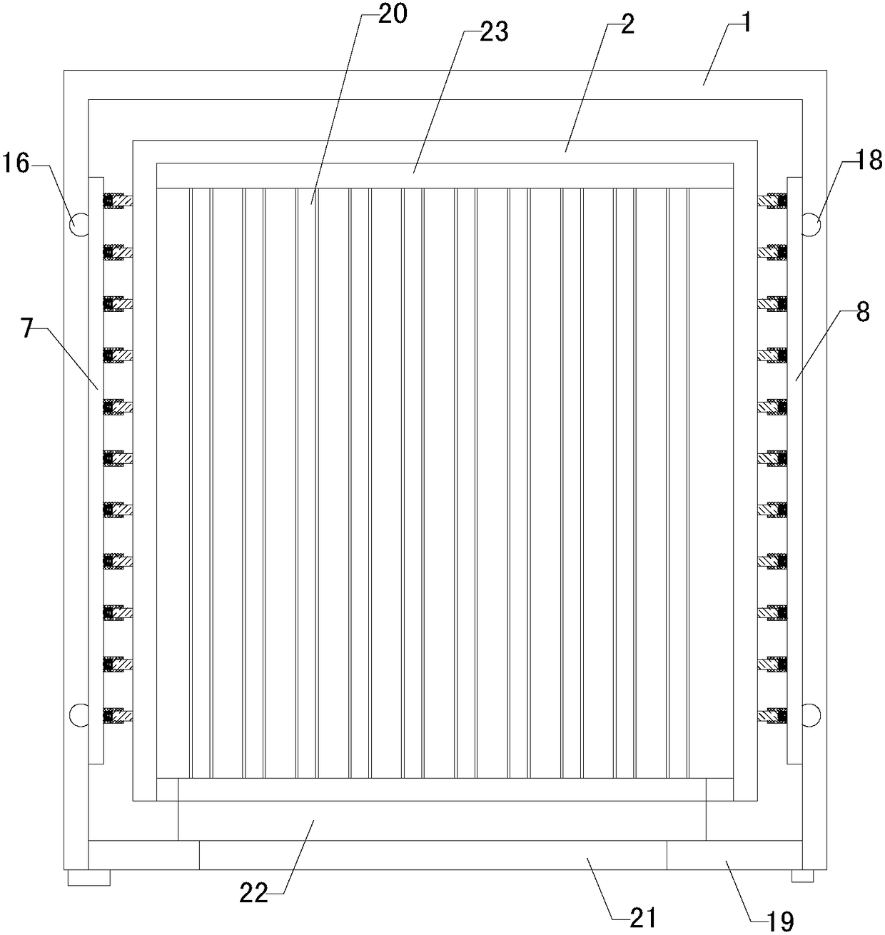
[0018] Such as Figure 1 to Figure 5 As shown, a liquid crystal display module damping device of the present invention comprises an outer box body 1, an inner box body 2, multiple sets of posts 3, multiple sets of upper springs 4 and multiple sets of lower springs 5, and the inside of the outer box body There is a placement cavity, the inner box is located in the placement cavity, the bottom ends of multiple sets of lower springs are connected with the inner bottom wall of the placement cavity, the top ends of multiple sets of lower springs are connected with the bottom end of the inner box, and multiple sets of post The bottom ends of the bottoms are all connected with t...


PUM


Abstract

The invention belongs to the technical field of a liquid crystal display module auxiliary device, and particularly relates to a liquid crystal display module damping device. The damping effect of on aliquid crystal display module in the vertical direction is improved, the protection to the liquid crystal display module is improved and practicability is improved; the effective protection of the liquid crystal display module is simultaneously achieved in the condition of emergency brake, the condition that a liquid crystal display is broken caused by squeezing of the liquid crystal display andreliability is improved. The damping device includes an out box body, an inner box body, an inserting column, an upper spring and lower spring, a rubber disk, a left sliding plate, a right sliding plate, a left guide sleeve, a guide pillar, a left spring, a right guide sleeve, a right guide pillar, a right spring, a left sliding pillar, a right sliding pillar and a clapboard; a taking and placingopening is formed in the front end of the out box body and a door plank is arranged at the taking and placing opening; an opening is formed in the front end of the inner box body; a placing cavity isarranged in the out box body, and a left sliding groove and a right groove are correspondingly formed in the left lateral wall and the right lateral wall of the placing cavity.

Description

technical field [0001] The invention relates to the technical field of liquid crystal display module accessory devices, in particular to a liquid crystal display module vibration damping device. Background technique [0002] As we all know, the liquid crystal display module shock absorber is an auxiliary device used to protect the liquid crystal display module during transportation, and it has been widely used in the field of liquid crystal display module processing and transportation; the existing The liquid crystal display module damping device includes a placement box, and a placement cavity is arranged inside the placement box, and multiple sets of vertical boards are arranged at equal intervals in the placement cavity, and both sides of the multiple groups of vertical boards are arranged There is a sponge layer, the top of the storage box is provided with a pick-and-place opening, and a door panel is arranged at the pick-and-place opening, and the left end of the door p...

Claims


Application Information

Patent Timeline
IPC IPC(8): B65D81/07B65D85/30
CPCB65D81/07B65D85/30
Inventor 任皖生
Owner 江苏聚龙显示科技有限公司
Features
  • R&D
  • Intellectual Property
  • Life Sciences
  • Materials
  • Tech Scout
  • Unparalleled Data Quality
  • Higher Quality Content
  • 60% Fewer Hallucinations
Learn More