A water pipe automatic storage device
A technology for storage devices and water pipes, which is applied in the directions of transportation and packaging, thin material handling, and delivery of filamentous materials. It can solve the problems of low efficiency, cumbersomeness, and no good collection method for water pipes, etc., and achieve convenient rolling and flexible operation. Effect
- Summary
- Abstract
- Description
- Claims
- Application Information
AI Technical Summary
Problems solved by technology
Method used
Image
Examples
Embodiment 1
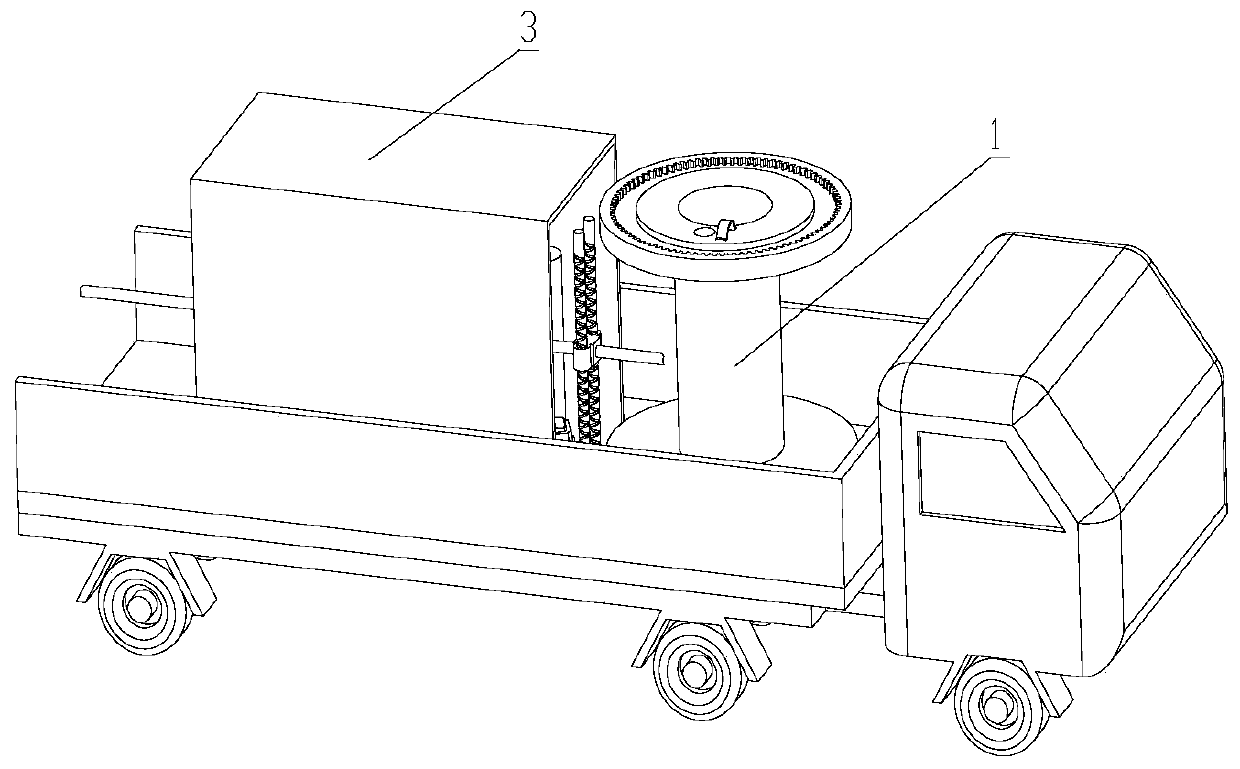
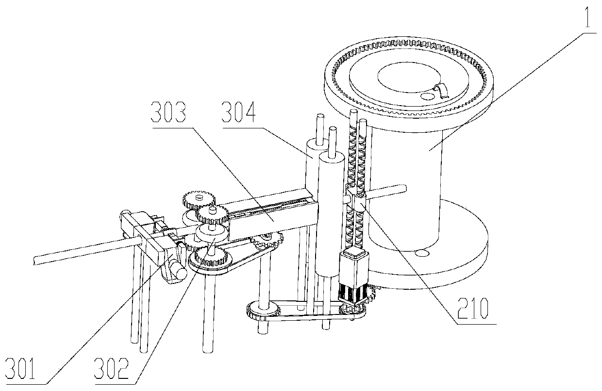
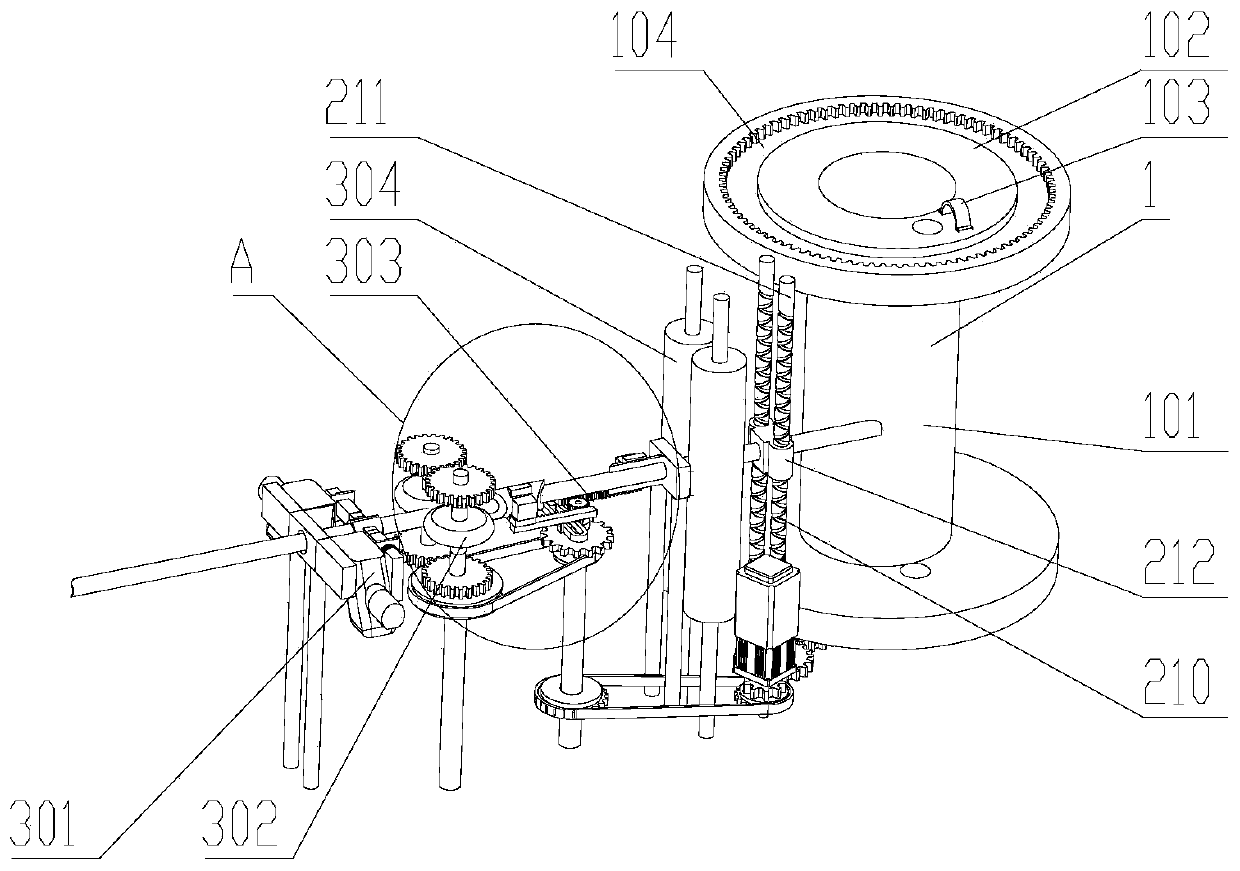
[0059] see Figure 1-7
[0060] The invention provides an automatic storage device for water pipes, which includes a pipe collection mechanism arranged on the car body;
[0061] The tube receiving mechanism includes a tube winding mechanism for fixing and rotating the tube shaft 1, and a tube pulling mechanism 3 arranged on one side of the tube winding mechanism for pulling the water pipe;
[0062] The pipe winding mechanism includes a base, on which the pipe shaft 1 is plugged; the driving mechanism drives the pipe shaft 1 to rotate; the water pipe to be stored is fixed on the pipe shaft 1 after passing through the pipe pulling mechanism 3;
[0063] The tube pulling mechanism 3 includes an inlet and an outlet, and hot air blowers 301 are arranged on both sides of the inlet.
[0064] The drive mechanism uses the motor as the power source, and the gear combination as the power transmission mechanism. (not shown in the figure)
Embodiment 2
[0066] Others are the same as in Embodiment 1, except that the tube shaft 1 includes a shaft body 101 in the middle and baffles 102 provided at both ends of the shaft body 101; a through hole 4 is provided on the baffle plate 102 near the shaft body 101, and the through hole Four inner diameters are greater than the outer diameter of the water pipe, and the outside of the baffle plate 102 is provided with a semicircular hoop 103, the hoop 103 is arranged on one side of the through hole 4 on the baffle plate 102, one end of the hoop 103 is hinged with the baffle plate 102, and the other end It is locked and connected with the baffle plate 102 through a lock; the baffle plate 102 is a circular plate.
Embodiment 3
[0068] On the basis of Embodiment 2, an annular groove 104 is provided on the outer surface of the baffle plate 102, and a ring gear is arranged in the groove body of the annular groove 104. The ring gear meshes with the driving gear of the tube shaft 1, and the driving gear of the tube shaft 1 is driven by the driving mechanism.
[0069] The drive mechanism uses the motor as the power source, and the gear combination as the power transmission mechanism.
PUM
 Abstract
Description
Claims
Application Information
 - R&D
- Intellectual Property
- Life Sciences
- Materials
- Tech Scout
- Unparalleled Data Quality
- Higher Quality Content
- 60% Fewer Hallucinations
Browse by: Latest US Patents, China's latest patents, Technical Efficacy Thesaurus, Application Domain, Technology Topic, Popular Technical Reports.
© 2025 PatSnap. All rights reserved.Legal|Privacy policy|Modern Slavery Act Transparency Statement|Sitemap|About US| Contact US: help@patsnap.com


