
Composite segment

A technology of composite segment and concrete structure, applied in the field of composite segment, can solve the problems of limited application, high cost, difficult to change shape, etc., to achieve the effect of realizing the value of steel mold, reducing production cost and increasing cost

Active Publication Date: 2020-12-01
SHANGHAI TUNNEL ENG CO LTD
View PDF7 Cites 0 Cited by
  • Summary
  • Abstract
  • Description
  • Claims
  • Application Information

AI Technical Summary

Problems solved by technology

Reinforced concrete segments are widely used in shield tunnels due to their good mechanical properties and low cost, and can meet engineering requirements in most working conditions, but sometimes in interval tunnels it is necessary to Partial sections or even full-section openings, such as the setting of connecting passages in subway tunnels and highway tunnels, at this time, reinforced concrete segments will not meet the design requirements, and designers often use steel pipes with better mechanical properties in this case piece
However, the processing precision of the steel pipe sheet is high (especially the concave-convex part of the edge), and the cost is high, which limits the application of the steel pipe sheet to a certain extent.
In addition, if the part or even the whole section of the cheap concrete segment is opened, the strength of the concrete after molding is high, the shape is difficult to change, and the machinability is poor, which greatly limits its application under complex working conditions. Applications

Method used


Image

  • Composite segment
  • Composite segment
  • Composite segment

Examples


Embodiment Construction

[0023] In order to facilitate the understanding of the present invention, the following will be described in conjunction with the accompanying drawings and embodiments.

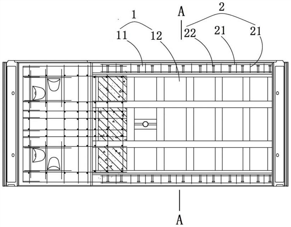
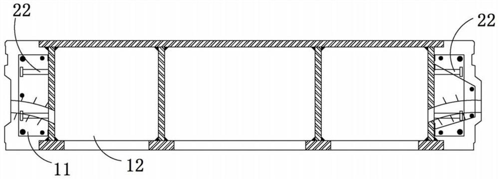
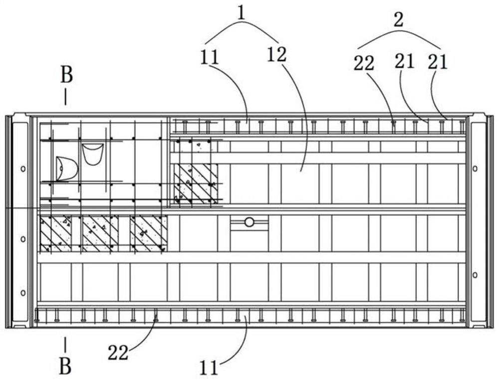
[0024] see Figures 1 to 4 As shown, the present invention provides a composite segment 1, which includes two concrete structures 11 arranged on both sides in the longitudinal direction and a steel structure 12 sandwiched between the two concrete structures 11, the steel structure 12 and the concrete structure 11 at the interface fixed with a connector 2 to connect the concrete structure 11 and the steel structure 12, the concrete structure 11 is the annular joint of the composite segment 1 for The assembled connection of the adjacent composite segments 1; the two concrete structures 11 are machinable concrete structures, one of the two concrete structures 11 is formed into a tenon (not shown in the figure), and the other of the two concrete structures 11 One is formed into a concave tenon (not shown in the ...


PUM

PropertyMeasurementUnit
densityaaaaaaaaaa
densityaaaaaaaaaa
densityaaaaaaaaaa

Abstract

The invention provides a composite segment, which comprises two concrete structures arranged on both sides along the longitudinal direction and a steel structure arranged between the two concrete structures. A connecting piece is fixed at the interface between the steel structure and the concrete structure for connecting the concrete structure and the steel structure, and the concrete structure isthe ring-directional joint of the composite segment; the two concrete structures are both machinable concrete structures, one of the two concrete structures is formed into a tenon, and the other concrete structure is formed into a blind mortise, wherein the shapes and sizes of the tenon an the blind mortise are matched with each other, which makes the adjacent composite segments matched with eachother through the tenon and the blind mortise. According to the invention, by utilizing the concrete structure instead of the steel pipe sheet tenon and blind mortise, not only the good performance of compression, bending and shear resistance can be guaranteed, but also the production cost can be effectively reduces.

Description

technical field [0001] The invention relates to the technical field of shield tunneling segments, in particular to a composite segment. Background technique [0002] The construction technology of shield tunnel segment assembly has been widely used in tunnel projects such as subways, highways, and drainage at home and abroad. Reinforced concrete segments are widely used in shield tunnels due to their good mechanical properties and low cost, and can meet engineering requirements in most working conditions, but sometimes in interval tunnels it is necessary to Partial sections or even full-section openings, such as the setting of connecting passages in subway tunnels and highway tunnels, at this time, reinforced concrete segments will not meet the design requirements, and designers often use steel pipes with better mechanical properties in this case piece. However, the processing precision of the steel pipe sheet is high (especially the concave-convex part of the edge), and t...

Claims


Application Information

Patent Timeline
Patent Type & Authority Patents(China)
IPC IPC(8): E21D11/08C04B28/00
CPCC04B28/00E21D11/08E21D11/086C04B16/04C04B14/06C04B14/28C04B2103/0068
Inventor 张衍宿文德翟一欣朱雁飞朱卫杰杨燕熊胜庄欠伟孙皓万敏赵玉同
Owner SHANGHAI TUNNEL ENG CO LTD
Learn More