Electromagnetic fan clutch

An electromagnetic fan and clutch technology, which is applied in the direction of machines/engines, coolant flow control, engine components, etc., can solve the problem of wire retention between the iron core part and the pulley, the deterioration of the compactness of the fan clutch, and the reduction of the assembly process Convenience and other issues, achieve good fixing effect, reduce load, and facilitate assembly

Pending Publication Date: 2018-09-11
ZHEJIANG NESSRAL MACHINERY
View PDF2 Cites 1 Cited by
  • Summary
  • Abstract
  • Description
  • Claims
  • Application Information

AI Technical Summary

Problems solved by technology

After the gap between the pulley and the core part is enlarged, the compactness of the fan clutch will become poor, and the volume of the fan clutch will increase and occupy more space, which is not conducive to energy saving and emission reduction when installed on vehicles and mechanical devices; while the gap The increase is too small and will not significantly improve the ease of assembly
After marking on the wire, pulling the wire in place during installation shows that there is no excess wire being squeezed between the core part and the pulley, but if the marking is in the wrong position, it will reduce the convenie

Method used


Image

  • Electromagnetic fan clutch
  • Electromagnetic fan clutch
  • Electromagnetic fan clutch

Examples


Example Embodiment

[0052] Embodiment one

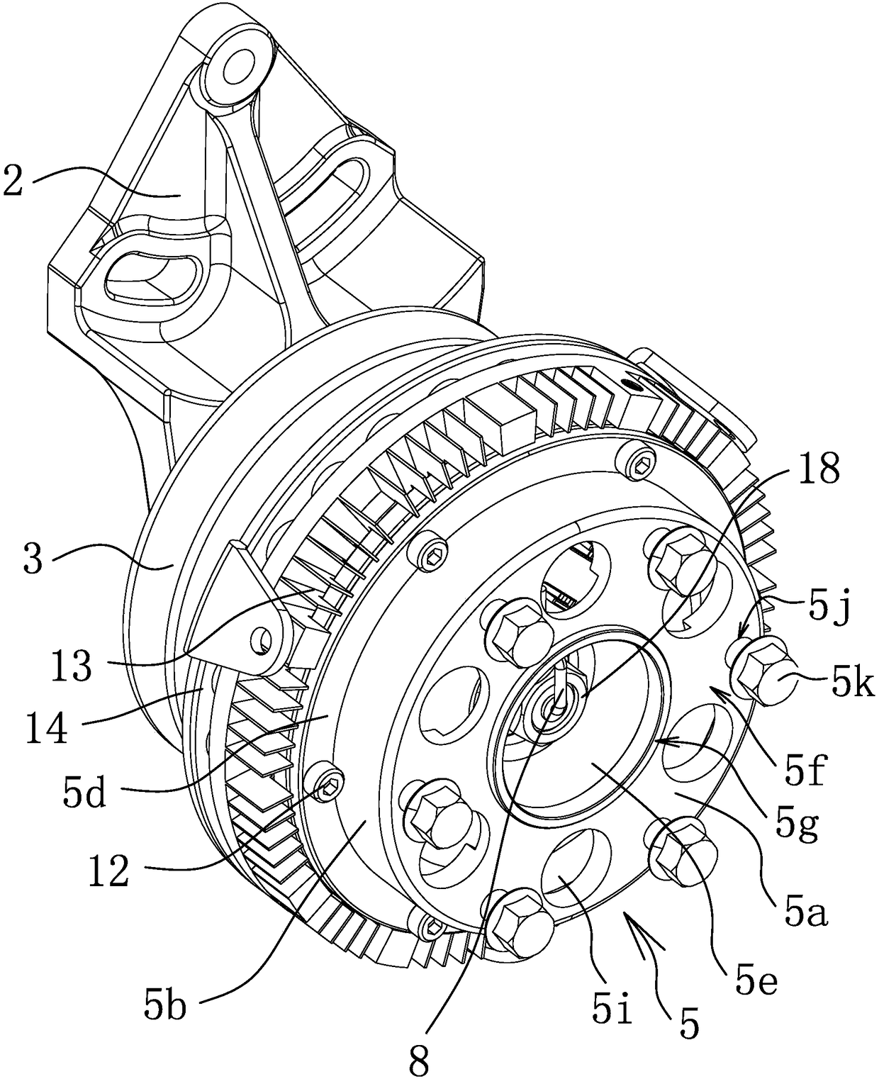
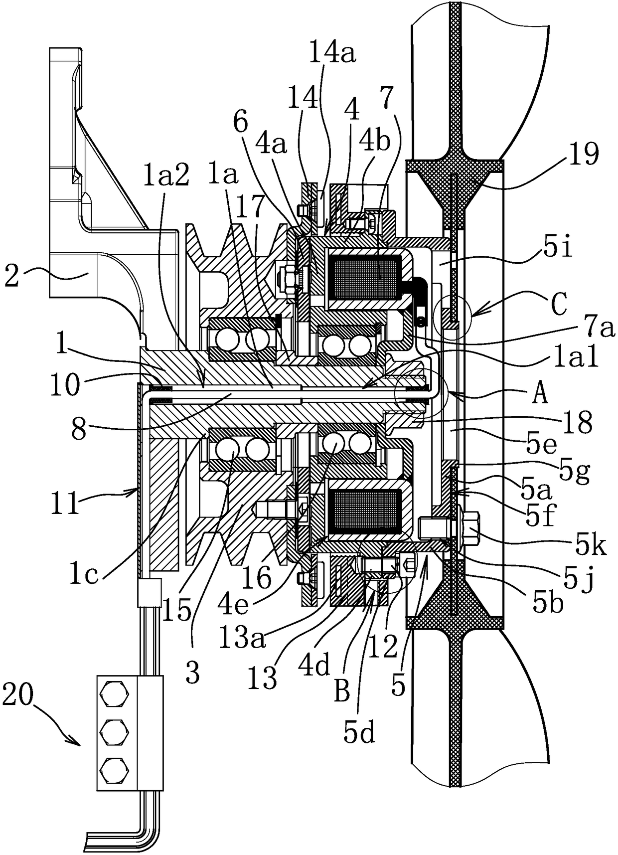
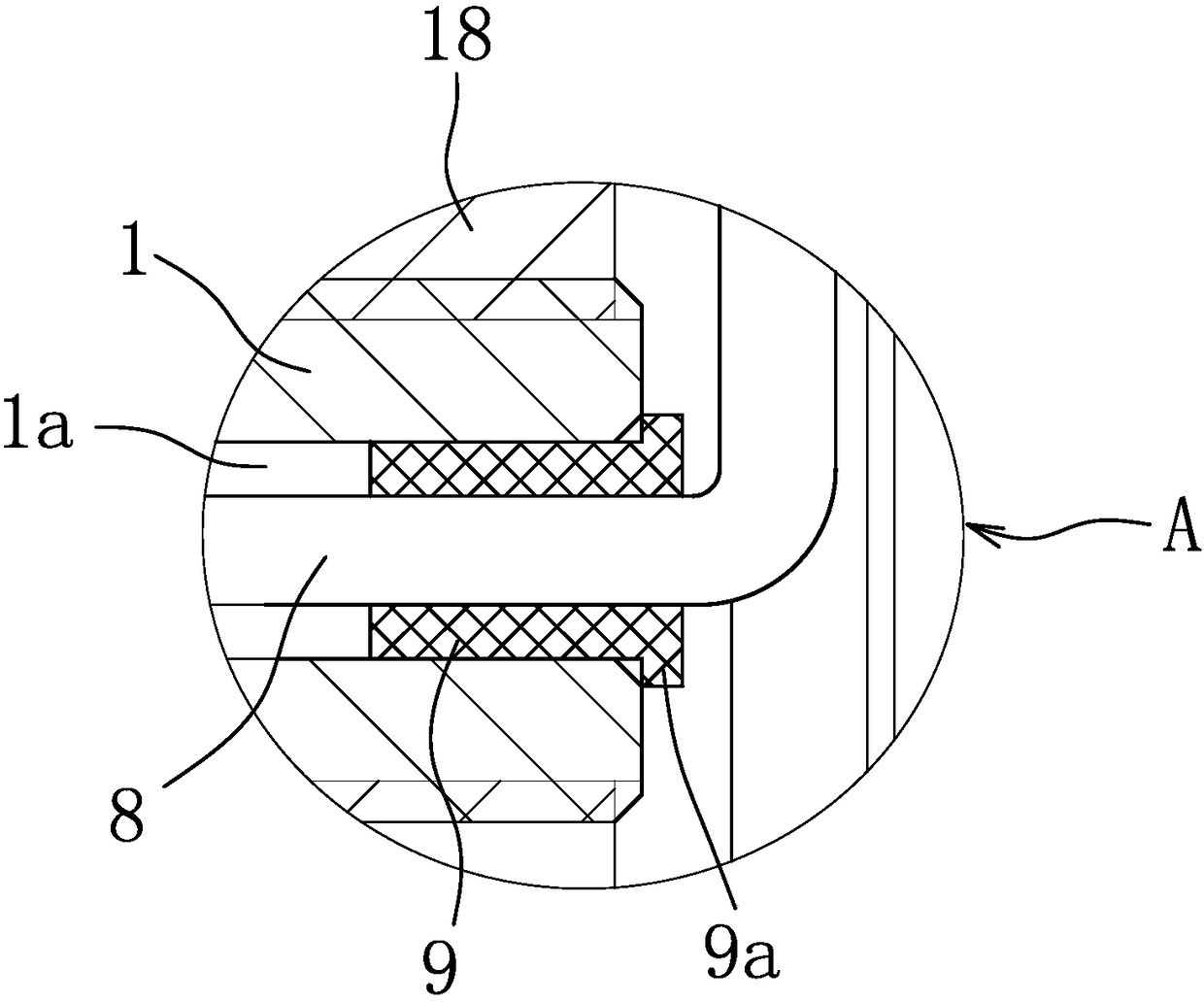
[0053] like Figure 1-Figure 6 As shown, an electromagnetic fan clutch includes a swing arm shaft 1, the rear end of the swing arm shaft 1 is sheathed and fixed with a swing arm frame 2, and the electromagnetic fan clutch is fixed beside the engine through the swing arm frame 2. The swing arm shaft 1 is also sheathed with a pulley 3 and a magnetic disk 4, both of which are rotatably connected to the swing arm shaft 1, and the pulley 3 is located between the swing arm frame 2 and the magnetic disk 4. A bearing one 15 is arranged between the pulley 3 and the swing arm shaft 1, a bearing two 16 is arranged between the magnetic disk 4 and the swing arm shaft 1, and a bearing two 16 is arranged between the swing arm shaft 1 and the bearing one 15 and the bearing two 16. Spacer 17. Both sides of the disk 4 are correspondingly provided with a coupling assembly 6 and a coil core assembly 7 , the coupling assembly 6 is connected to the pulley 3 , and the coil ...


PUM


Abstract

The invention provides an electromagnetic fan clutch and belongs to the technical field of machinery. The electromagnetic fan clutch solves the problems that existing electromagnetic fan clutches areinconvenient to assemble and the like. The electromagnetic fan clutch comprises a swing arm shaft and a fan connecting disc, wherein a magnetic disc and a belt wheel are rotatably connected to the swing arm shaft; a coupling assembly and a coil iron core assembly are correspondingly arranged on two sides of the magnetic disc; the coil iron core assembly is fixedly connected to the swing arm shaftand is connected to a guide wire; the coupling assembly is connected to the belt wheel; the fan connecting disc is suspended out of the swing arm shaft and is fixedly connected to the magnetic disc; athrough hole penetrating through the front and back ends of the swing arm shaft is formed in the swing arm shaft; and a guide wire is arranged through the through hole. The electromagnetic fan clutchhas the advantages of being convenient to assemble, high in working stability, energy-saving and emission-reducing and the like.

Description

technical field [0001] The invention belongs to the technical field of machinery and relates to an electromagnetic fan clutch. Background technique [0002] When the engine is running, the radiator of the water tank is required to dissipate heat for the engine, and the radiator of the radiator is cooled by air. The radiator exchanges heat with the air outside the radiator, thereby transferring the heat in the radiator to the air. When the air flows, it brings cold air, so that the heat in the radiator of the water tank is transmitted to the air, so that the heat on the outer surface of the radiator of the water tank is continuously taken away, and the temperature of the water tank is cooled. When the cold water in the water tank passes through the engine, it passes through the heat exchange. Cool down the engine continuously. In order to improve the heat dissipation efficiency, it is necessary to carry out forced convection to the air outside the radiator, and generally a ...

Claims


Application Information

Patent Timeline
IPC IPC(8): F01P7/08
CPCF01P7/081
Inventor 徐时聪樊美刚
Owner ZHEJIANG NESSRAL MACHINERY
Why Eureka
Try Eureka