
A modified air compressor casing

A compressor and air extractor technology, which is applied in the direction of machine/engine, mechanical equipment, engine ignition, etc., and can solve the problem of sucking low-pressure stall air mass and other problems

Active Publication Date: 2019-04-05
TSINGHUA UNIV
View PDF6 Cites 0 Cited by
  • Summary
  • Abstract
  • Description
  • Claims
  • Application Information

AI Technical Summary

Problems solved by technology

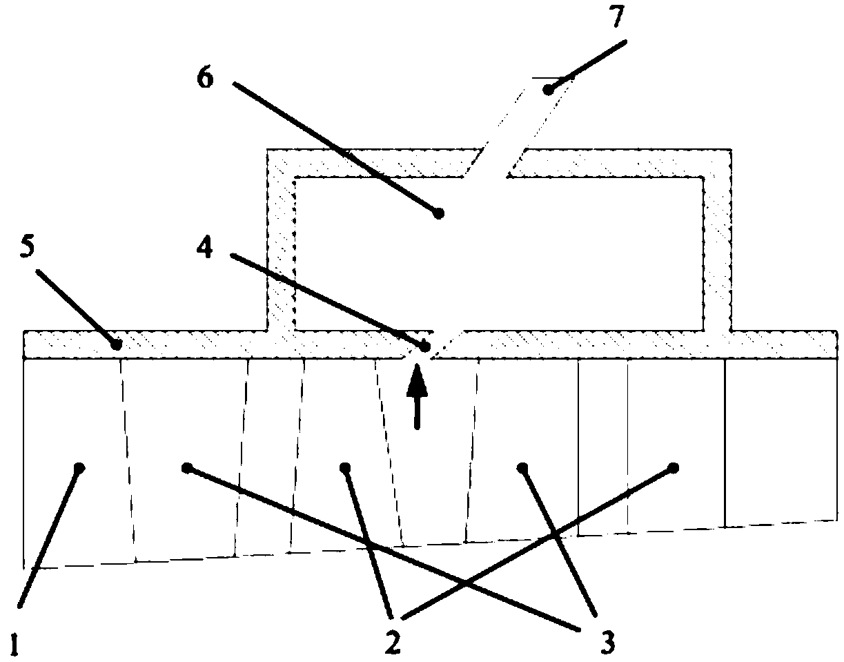
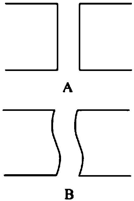
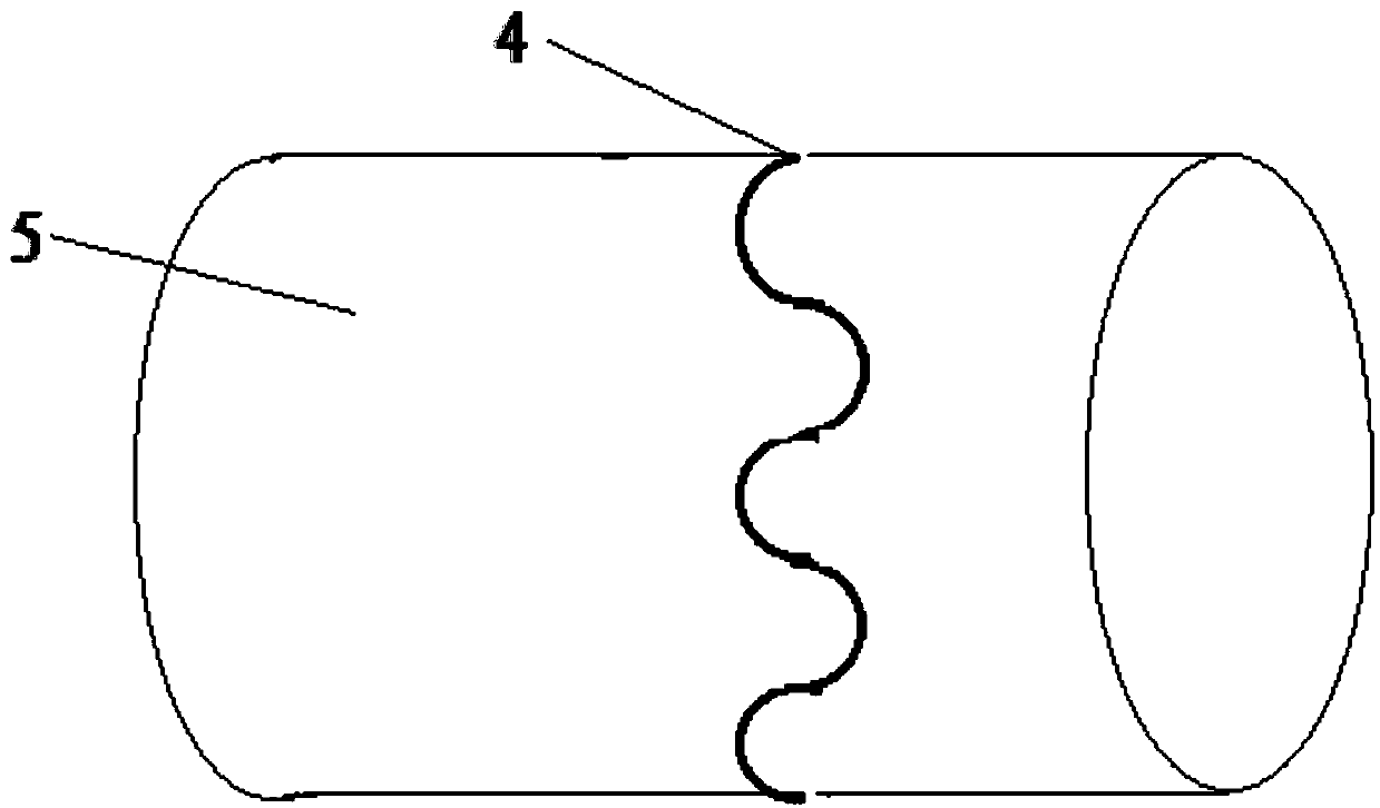
[0005] In order to solve the problem that the current traditional axially symmetrical casing mechanism cannot suck the low-pressure stalled air mass well, the present invention provides a modified compressor air extraction casing, including: a compressor casing and an air extraction casing, The air extraction casing is sleeved on the compressor casing; a casing channel is provided on the circumference of the side wall of the compressor casing, and the casing channel penetrates through the compressor casing. On the side wall, the compressor casing communicates with the air extraction casing through the casing channel; the shape of the casing channel is a circumferential curve composed of complex linear periodic repetitions

Method used


Image

  • A modified air compressor casing
  • A modified air compressor casing
  • A modified air compressor casing

Examples


Embodiment Construction

[0023] The specific implementation manners of the present invention will be further described in detail below in conjunction with the accompanying drawings and embodiments. The following examples are used to illustrate the present invention, but are not intended to limit the scope of the present invention.

[0024] In the description of the present invention, it should be noted that the orientations or positional relationships indicated by the terms "middle", "upper", "lower", "inner" and "outer" are based on the orientations or positional relationships shown in the drawings , is only for the convenience of describing the present invention and simplifying the description, but does not indicate or imply that the referred device or element must have a specific orientation, be constructed and made in a specific orientation, and thus should not be construed as limiting the present invention.

[0025] In the description of the present invention, it should be noted that unless other...


PUM


Abstract

The invention provides a modified compressor air pumping casing. The modified compressor air pumping casing comprises a compressor casing body and an air pumping casing body; the air pumping casing body sleeves the compressor casing body; a casing channel is formed in the circumferential direction of the side wall of the compressor casing body and penetrates through the side wall of the compressorcasing body; the compressor casing body communicates with the air pumping casing body through the casing channel; and the casing channel is shaped like a complex linear periodic repeatedly-composed circumferential curve. According to the modified compressor air pumping casing, the shape of a traditional circumferential symmetric air pumping casing body is changed into the complex linear periodicrepeatedly-composed circumferential curve from a circumferential straight line surrounding the outer wall of the compressor casing body, so that the on-way resistance of migration of air mass in the circumferential direction of an air pumping channel can be increased, the obstruction effect on the low-pressure separated air mass pumped away from a compressor passage due to the migration of the high-pressure airflow in the circumferential direction of an air pumping channel seam can be weakened, the flow separation can be relieved more easily, the surge phenomenon caused by the intensified rotating stall of gas in the compressor casing body can be effectively avoided, and a gas turbine can be started more stably and safely.

Description

technical field [0001] The invention relates to the field of gas turbines, in particular to a modified compressor air extraction casing. Background technique [0002] Gas turbine is an important technical equipment to realize efficient and clean transformation of energy and ensure national energy security. A gas turbine consists of three parts: a compressor, a combustor and a turbine. Among them, the flow in the compressor contains complex reverse pressure gradient flow. During the start-up process, due to the small flow rate, it is easy to cause a rotating stall and cause surge, resulting in a major safety accident. During the start-up process of the gas turbine, the rotor speed is constantly changing, and the compressor is working in an unbalanced working state. It is necessary to extract air from the compressor to prevent the occurrence of rotating stall, so as to ensure the safe start of the gas turbine. [0003] The channel of the traditional compressor air extraction...

Claims


Application Information

Patent Timeline
Patent Type & Authority Patents(China)
IPC IPC(8): F04D27/02F02C7/26
CPCF02C7/26F04D27/0215
Inventor 李雪松任晓栋顾春伟王岩
Owner TSINGHUA UNIV
Learn More