

Anti-snake oil pressure shock absorber with variable damping, rail train and its design method
A technology for hydraulic shock absorbers and rail trains, applied in shock absorbers, liquid shock absorbers, shock absorbers, etc., can solve problems such as damage to the cylindrical surface of the piston, affect the life of the piston seal, and difficult processing of the damping groove, etc., to achieve Inhibit snaking movement, good pressure relief effect, and improve driving safety
- Summary
- Abstract
- Description
- Claims
- Application Information
AI Technical Summary
Problems solved by technology
Method used
Image

Examples
Embodiment 1
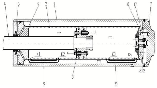
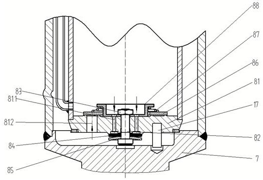
[0037] The variable damping anti-serpentine oil pressure shock absorber includes an oil storage cylinder 1, a pressure cylinder 2 coaxially arranged in the oil storage cylinder 1, a piston 3 installed in the cylinder force cylinder 2, and one end is fixed to the piston 3 and the other end is extended. Out of the piston rod 4 at the front end of the oil storage cylinder 1, the guide seat 5 that is installed in the oil storage cylinder 1 and guides and cooperates with the piston rod 4, and the outer screw cap 6 that is threaded with the oil storage cylinder 1 and covers the front end of the oil storage cylinder 1, and is installed in the oil storage cylinder 1. The chassis 7 at the rear end and the bottom valve 8 that covers the rear end of the pressure cylinder 2 and can conduct oil inside and outside the pressure cylinder 2 under the action of oil pressure. The guide seat 5 is covered at the front end of the pressure cylinder 2. The piston 3 connects the pressure cylinder The i...
Embodiment 2
[0048] The difference from Embodiment 1 is that the front pressure relief channel 9 and the rear pressure relief channel 10 are annular channels coaxially arranged with the pressure cylinder 2, and the oil storage chamber III is set in the same way as the pressure cylinder 2. The front sleeve 11 and the rear sleeve 12 of the shaft, the front sleeve 11 and the rear sleeve 12 are sealed and fixed with the outer wall of the pressure cylinder 2, and the front sleeve 11 is close to the guide seat 5, forming a front The pressure relief channel 9 , the rear sleeve 12 is close to the bottom valve 8 , and the rear pressure relief channel 10 is formed between the pressure cylinder 2 . The working principle of this embodiment is the same as that of the first embodiment. Compared with the liquid oil pipeline in the first embodiment, the installation structure of the front sleeve 11 and the rear sleeve 12 is relatively simpler, and the oil passing capacity is relatively larger.
[0049] Th...
PUM
 Abstract
Description
Claims
Application Information