Catheterization drainage device for thoracic cavity

A technology for placing tubes and thoracic cavity, which is applied in the direction of catheters, trocars, suction instruments, etc., which can solve problems such as troubles, affecting the recovery of patients, and prolonging operation time.

Active Publication Date: 2018-09-14
WENZHOU CENT HOSPITAL
View PDF5 Cites 4 Cited by
  • Summary
  • Abstract
  • Description
  • Claims
  • Application Information

AI Technical Summary

Problems solved by technology

[0003] When there is too much effusion in the pleural cavity, it is often necessary to repeatedly pump fluid, rinse, and inject medicine; the traditional chest tube drainage device mainly includes an outer tube, a piston tube for pumping fluid, and a puncture needle for puncturing; In this case, the puncture needle needs to be inserted into the chest cavity of the patient first, and after entering the human body to a certain depth, the puncture needle is pulled out, and the outer tube is fixed with adhesive tape to facilitate liquid extraction; due to the different physical conditions of each patient, the piston tube enters the human body The depth of the puncture needle is also slightly different, and it is often necessary to adjust the depth of the puncture needle into the patient several times before the fluid can be drawn; in each fine-tuning, the original tape needs to be torn off first, and then the outer tape is re-fixed with the tape after the fine-tuning is completed. It is very troublesome and prolongs the operation time, which is easy to cause other injuries to the patient and affects the recovery of the patient.

Method used


Image

  • Catheterization drainage device for thoracic cavity
  • Catheterization drainage device for thoracic cavity
  • Catheterization drainage device for thoracic cavity

Examples


Embodiment Construction

[0019] The present invention will be described in further detail below in conjunction with the accompanying drawings and embodiments. Wherein the same components are denoted by the same reference numerals.

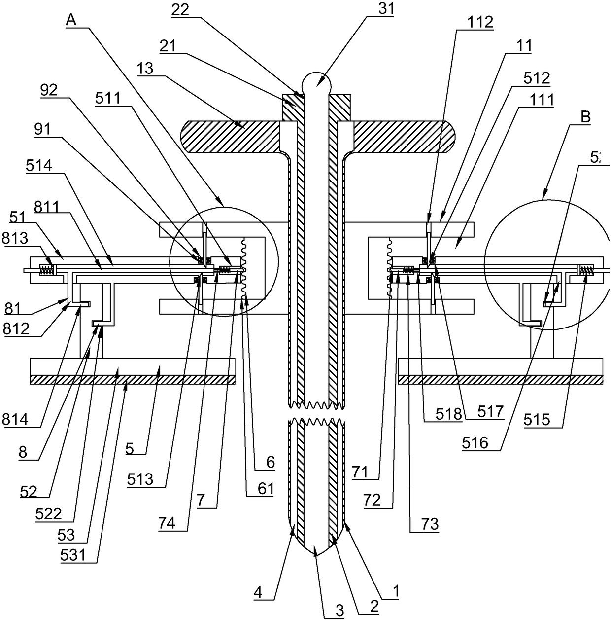
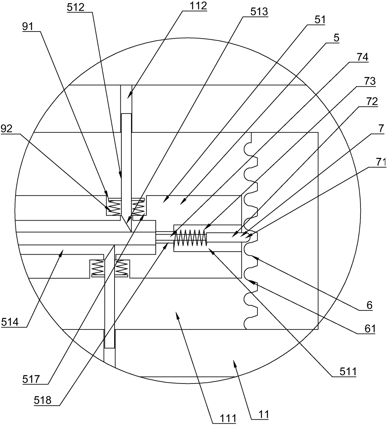
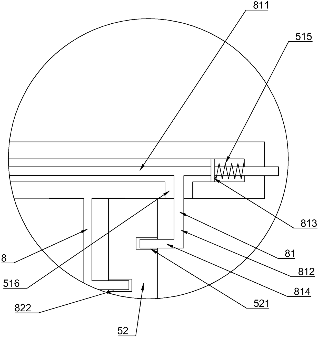
[0020] refer to Figures 1 to 4 As shown, a chest tube drainage device in this embodiment includes an outer tube 1, a piston tube 2, a probe 3 and a seal 4, the piston tube 2 is sleeved in the outer tube 1, and the probe 3 is socketed in the piston tube 2, the seal 4 is located between the piston tube 2 and the outer tube 1; one end of the probe 3 protrudes from the piston tube 2; the outer tube 1 is provided with a connecting plate 11 , the connecting plate 11 is fixedly connected with the outer tube 1, the connecting plate 11 is provided with a fixing assembly 5 for fixing the outer tube 1 on the human body, and the fixing assembly 5 includes a sliding block 51, a connecting block 52 and a fixing block 53, the fixed block 53 is provided with an adhesive layer 531 for t...


PUM


Abstract

The invention discloses a catheterization drainage device for a thoracic cavity. The device includes an outer pipe, a piston pipe, a probe and a sealing component; the piston pipe is sleeved with theouter pipe, and the sealing component is positioned between the outer pipe and the piston pipe and used for preventing gas or a body fluid in the thoracic cavity from overflowing after the device is placed into the thoracic cavity and the piston pipe is removed; one end of the probe extends out of the piston pipe to provide convenience for placing the device into the thoracic cavity of a patient;a connecting plate is arranged on the outer wall of the outer pipe, and a fixing assembly is arranged on the connecting plate and used for fixing the outer pipe to the human body; the fixing assemblyconsists of a sliding block, a connecting block and a fixing block, a bonding layer is arranged on the fixing block and has great stickiness, it is ensured that the fixing block can be firmly bonded to the skin of the human body, and therefore the outer pipe is fixed; meanwhile, according to the insertion depth of the outer pipe in the human body, the sliding block can move in the axial directionof the outer pipe, and convenience is provided for smoothly extracting hydrops in the thoracic cavity of the patient to make the patient recover as soon as possible.

Description

technical field [0001] The invention relates to the technical field of medical devices, in particular to a chest tube drainage device. Background technique [0002] The pleural cavity is a potential space between the lungs and the chest wall, and the visceral and parietal pleura normally appear to be covered with a thin layer of fluid that lubricates the lungs during respiratory movements. The pleural cavity and the fluid in it are not in a static state, and the shape and pressure of the pleural cavity change greatly during each breathing cycle, so that the fluid in the pleural cavity is continuously filtered out and absorbed and is in a dynamic balance. Various factors cause the fluid in the pleural cavity to form too quickly or absorb too slowly, resulting in pleural effusion. [0003] When there is too much effusion in the pleural cavity, it is often necessary to repeatedly pump fluid, rinse, and inject medicine; the traditional chest tube drainage device mainly includes...

Claims


Application Information

Patent Timeline
Patent Type & Authority Applications(China)
IPC IPC(8): A61M1/00A61B17/34A61M25/02
CPCA61B17/3415A61B17/3421A61B2017/3419A61M1/0023A61M25/02A61M2025/0253A61M2025/028
Inventor 吴正兴蒋贤高施伎蝉
Owner WENZHOU CENT HOSPITAL
Why Eureka
Try Eureka