Crank shaft lathe center frame device

A crankshaft lathe and center rest technology, applied in auxiliary devices, turning equipment, turning equipment, etc., can solve the problems of low quality, unstable crankshaft rotation and processing, crankshaft deviation, etc., to improve quality and efficiency, and ensure stability. , the effect of reducing friction

Pending Publication Date: 2018-09-14
QINGDAO HAIXI HEAVY IND
View PDF9 Cites 1 Cited by
  • Summary
  • Abstract
  • Description
  • Claims
  • Application Information

AI Technical Summary

Problems solved by technology

[0004] Aiming at the problem that the existing crankshaft with small self-weight has no limitation on the upper part of the crankshaft during rotation and processing, the rotation and processing of the crankshaft are unstable, resulting in deviation and low quality of the processed crankshaft. The present invention provides a crankshaft Lathe Steady Frame Device

Method used


Image

  • Crank shaft lathe center frame device
  • Crank shaft lathe center frame device
  • Crank shaft lathe center frame device

Examples


Embodiment Construction

[0022] The specific embodiment of the present invention will be further described below in conjunction with accompanying drawing and specific embodiment:

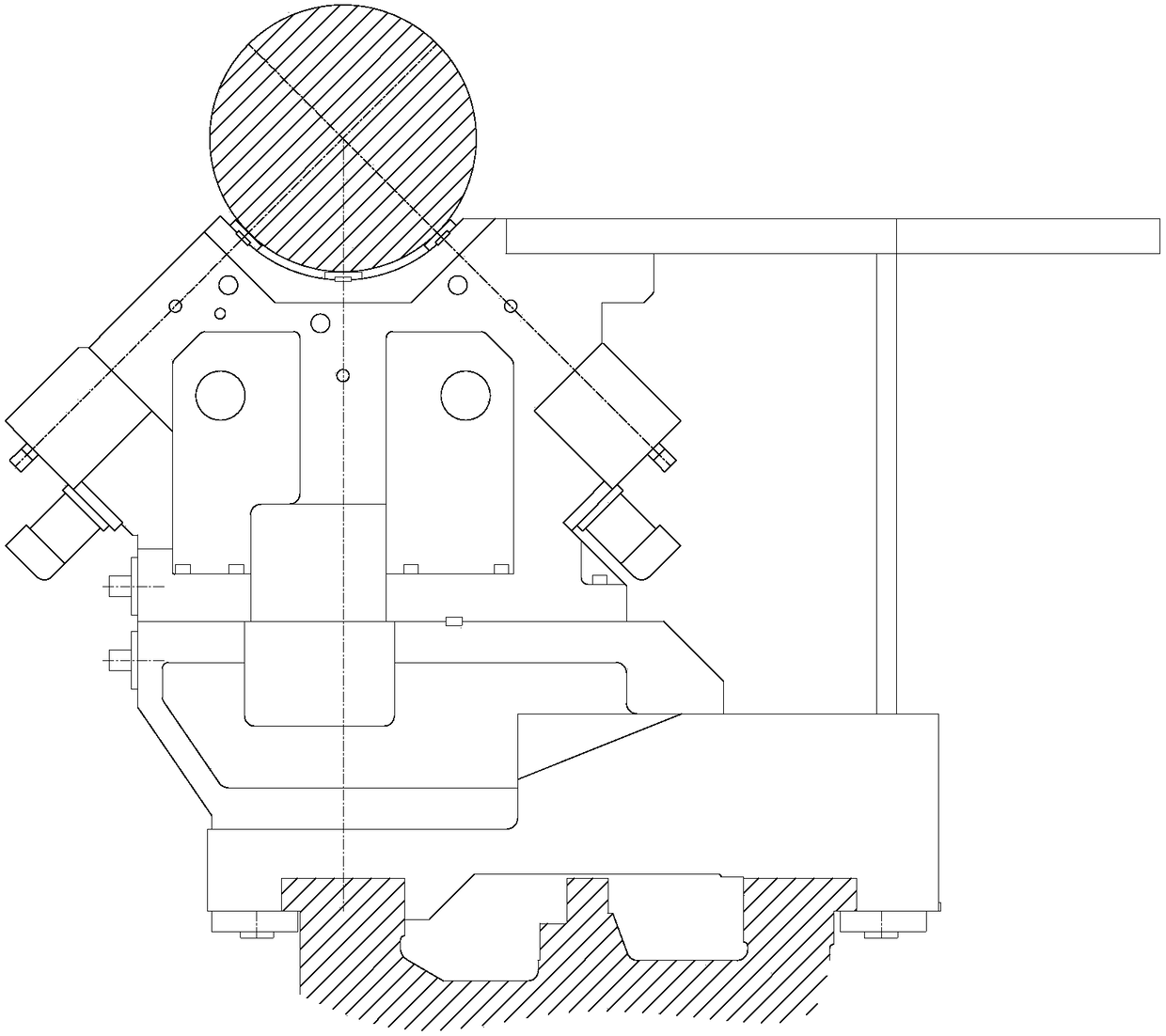
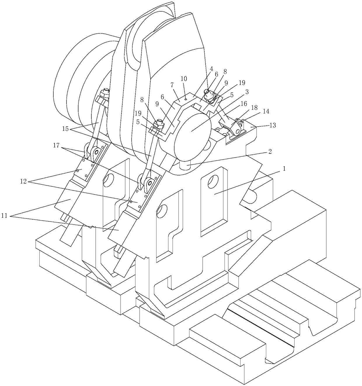
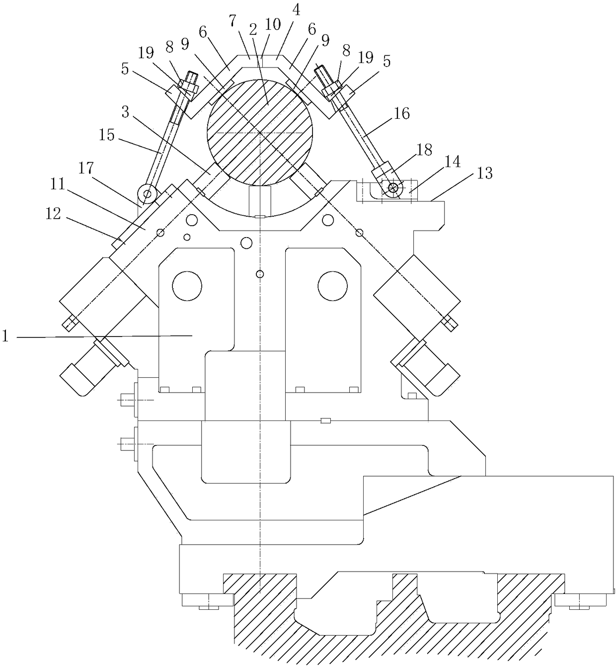
[0023] combine figure 2 with image 3 , a crankshaft lathe center frame device, including a center frame 1, in the middle of the center frame 1 is provided with three support columns 3 for supporting the main journal 2 of the crankshaft.

[0024] Two of the supporting columns are respectively arranged at a 45-degree inclination in the middle of the center frame, and the other supporting column is arranged in the center of the middle of the center frame, and the supporting column provides lower support for the main journal.

[0025] The center frame 1 is provided with a cover structure that can be stably pressed on the upper part of the main journal, and the cover structure provides upper stabilizing force for the main journal.

[0026] The cover plate structure includes a pressing plate 4, and both sides of the pressing ...


PUM

PropertyMeasurementUnit
diameteraaaaaaaaaa

Abstract

The invention provides a crank shaft lathe center frame device which comprises a center frame. Multiple support pillars for supporting a main journal of a crank shaft are arranged in the center of thecenter frame; a cover plate structure capable of stably and tightly pressing on the upper part of the main journal is arranged on the center frame; the support pillars on the center frame support thelower part of the main journal; the cover plate structure stably and tightly press on the upper part of the main journal and comprises a pressing plate; movable pull rods are inclinedly connected totwo sides of the pressing plate; the lower ends of the movable pull rods are hinged onto the center frame; and the movable pull rods tightly press the main journal onto the center frame through the pressing plate. An oil groove is formed in a contact surface of a babbitt alloy block and the main journal, and when the crank shaft rotates, the main journal is lubricated, so that the friction betweenthe main journal and the pressing plate is reduced. The cover plate structure covers and presses on the main journal so as to prevent the crank shaft from upwards bouncing when the crank shaft rotates and is processed, so that the stability in processing the crank shaft is ensured, and the processing quality and the processing efficiency of the crank shaft are improved.

Description

technical field [0001] The invention relates to the field of crankshaft processing lathes, in particular to a center frame device for crankshaft lathes. Background technique [0002] The overall turning of the crankshaft of high-horsepower low-speed diesel engine with a cylinder diameter of 500mm to 350mm is carried out on a special crankshaft lathe. During processing, multiple center frames of the machine tool respectively support each main journal of the crankshaft. Each supporting column, such as figure 1 shown. The entire crankshaft falls on the support column of the center frame, and there is no restriction above the crankshaft. [0003] When the crankshaft of a high-horsepower low-speed diesel engine to be processed weighs more than 20 tons, it can be turned and processed on a special lathe for the crankshaft at a low speed, and stable rotation and processing can be guaranteed by its own weight. However, when the weight of the crankshaft is less than 20 tons (bore l...

Claims


Application Information

Patent Timeline
Patent Type & Authority Applications(China)
IPC IPC(8): B23Q1/76B23Q11/10B23B5/18B23B25/00
CPCB23B5/18B23B25/00B23Q1/76B23Q1/763B23Q11/10
Inventor 陈鑫刘晓军余以忠万春民郜斌任敏吴侃李其昌曹维新赵勇葛艳美宋鲁鹏孙婷婷薛世祥张明山王夏绒蔡志书梅华峰吴志明刘俊新曾涛谭青春苗闯徐强赵艳强刘壮王永亮
Owner QINGDAO HAIXI HEAVY IND
Why Eureka
Try Eureka