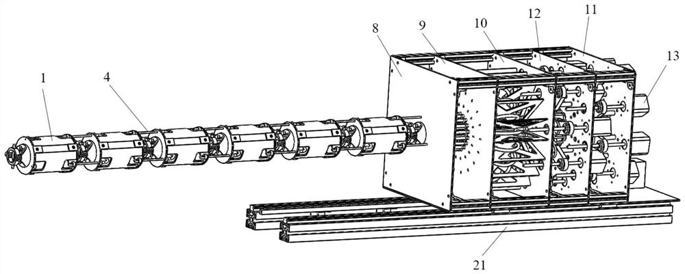
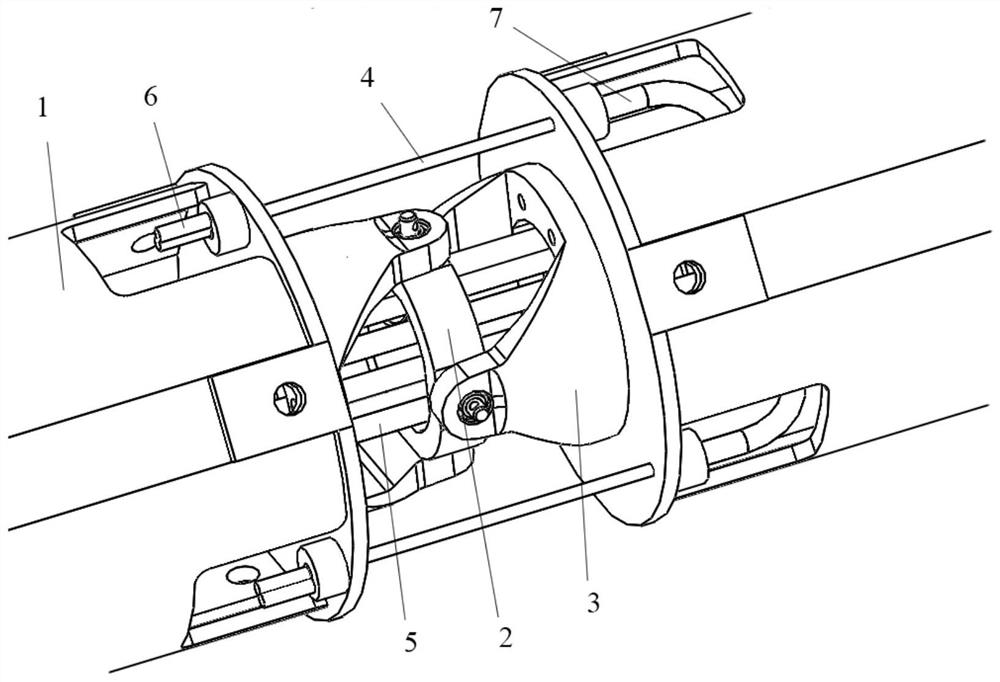
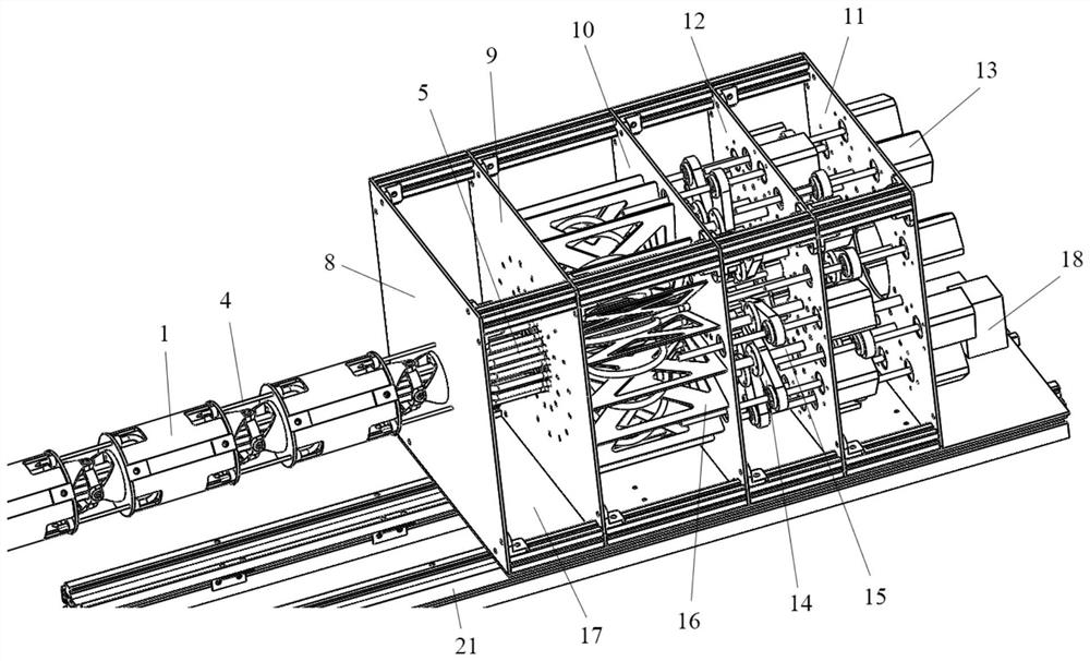
A multi-joint robotic arm

A multi-joint manipulator and manipulator technology, applied in the field of manipulators, can solve the problems of small number of joints, can only perform specific work, large size, etc., and achieve the effects of large flexibility, large degrees of freedom, and small size

Inactive Publication Date: 2020-10-16
BEIHANG UNIV
View PDF2 Cites 1 Cited by
  • Summary
  • Abstract
  • Description
  • Claims
  • Application Information

AI Technical Summary

Problems solved by technology

[0004] In view of the above analysis, the present invention aims to provide a multi-joint manipulator to solve the problem that the existing manipulators are bulky, have a small number of joints, and can only perform specific tasks

Method used


Image

  • A multi-joint robotic arm
  • A multi-joint robotic arm
  • A multi-joint robotic arm

Examples


Embodiment Construction

[0030] The preferred embodiments of the present invention will be described below in detail with reference to the accompanying drawings. The accompanying drawings constitute a part of the application and are used together with the embodiments of the present invention to explain the principle of the present invention, and are not used to limit the scope of the present invention.

[0031] Although traditional industrial robotic arms, such as those developed and produced by FANUC, KUKA, ABB, and Kawasaki, have played a huge role in promoting the intelligent development of today's factories, reducing labor costs and improving production efficiency, but The disadvantage of this type of traditional manipulator is that it requires specific production or programming, and can only work under specific working conditions. Therefore, these specific manipulators lose their usefulness when they need to enter a small space for work. For example, in the highly sophisticated and lightweight indust...


PUM


Abstract

The invention relates to a multi-joint mechanical arm and belongs to mechanical arms. The multi-joint mechanical arm is used for solving the problems that existing mechanical arms have large sizes, are provided with few joints, and can only carry out specific work. Any two adjacent joint units of the multi-joint mechanical arm are connected through a joint, and each joint is provided with a pulling wire for bending the multi-joint mechanical arm. The pulling wires penetrate into pulling wire tubes, and the pulling wire tubes penetrate into the multi-joint mechanical arm and are connected withan actuator. According to the multi-joint mechanical arm, the joints are driven to bend in the mode of combining the pulling wires and the wire tubes, so that accompanied rotation caused by the near-end joints to the far-end joints is avoided, and the control algorithm of the mechanical arm is simplified. The multiple joints small in axial size are used as arm bodies, the joints are sequentially connected through connecting pairs, and thus the whole multi-joint mechanical arm is small in size, large in degree of freedom, high in flexibility, and capable of stretching into the narrow and smallspace where a traditional mechanical arm cannot touch for working.

Description

Technical field [0001] The present invention relates to the technical field of mechanical arms, in particular to a multi-joint mechanical arm. Background technique [0002] In actual industrial engineering, there are many tasks for working in small spaces. Especially in the field of aerospace manufacturing, the installation of various components is very compact, making it very difficult to perform various operations such as detection, assembly, welding, and maintenance inside the assembly. For example, the screws in the wing box of the aircraft loose or fall off, causing safety hazards. In addition, there are also many problems involving small spaces in expedition, disaster relief and counter-terrorism. In short, whether in industry or life, military or civilian use, a flexible robotic arm that can adapt to small and dangerous spaces is needed. [0003] Although the traditional industrial robotic arm has a large load capacity, it has a large volume, a small number of joints, and...

Claims


Application Information

Patent Timeline
Patent Type & Authority Patents(China)
IPC IPC(8): B25J9/06B25J9/10B25J17/00
CPCB25J9/06B25J9/104B25J17/00
Inventor 刘磊曹晟阁裴旭于靖军李小强王越唐一超罗世福汤子湘田春皓
Owner BEIHANG UNIV
Why Eureka
Try Eureka