Wide-range optical fiber bending controllable device

A control device, a wide-ranging technology, used in the installation of optical fibers/cables, the use of optical devices to transmit sensing components, measurement devices, etc., can solve the problems of uncontrollable bending angle, limited number of measurement points, errors, etc., to avoid bending loss. , the effect of avoiding errors

Inactive Publication Date: 2018-09-14
NORTHEASTERN UNIV
View PDF4 Cites 1 Cited by
  • Summary
  • Abstract
  • Description
  • Claims
  • Application Information

AI Technical Summary

Problems solved by technology

[0003] In the original detection technology, for small curvature changes, it is generally chosen to paste the optical fiber on a flexible iron sheet, and use a displacement platform to fix the two ends for measurement. During the measurement, the change of the displacement platform will cause non-sensing optical fiber position changes, introducing other errors
The measurement of small curvature range generally adopts the method of standard cylinder. The disadvantage is that the bending angle is uncontrollable, and the number of measurement points is limited. Every change will change the shape of the sensing fiber and introduce other errors.

Method used


Image

  • Wide-range optical fiber bending controllable device
  • Wide-range optical fiber bending controllable device
  • Wide-range optical fiber bending controllable device

Examples


Embodiment

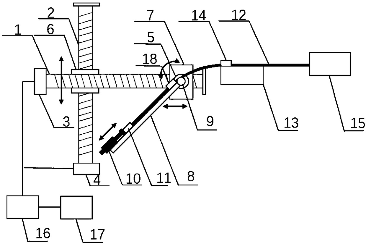
[0032] device such as figure 1 As shown, a large-range optical fiber bending adjustable device includes a rotary displacement unit, a control unit and an optical fiber fixing unit, and is characterized in that the rotary displacement unit includes an X screw slide 1, a Y screw slide 2, Stepping motor X3, stepping motor Y4, stepping motor Z5, moving platform Y6, moving platform X7 and optical fiber rotating fixed plate 8; among them, X screw slide 1 is fixed on Y screw slide 2 through moving platform Y6 , which is controlled by the stepper motor Y4 to move vertically on the Y screw slide 2; the stepper motor Z5 is fixed on the X screw slide 1 through the mobile platform X7, and is controlled by the stepper motor X3 to move on the X screw slide The bar slide table 1 moves in the horizontal direction; the optical fiber rotation fixing plate 8 is arranged on the stepper motor Z5 for controlling the rotation angle of the optical fiber; the optical fiber fixing unit includes an opti...


PUM


Abstract

The present invention provides a wide-range optical fiber bending controllable device. The device includes a rotary displacement unit, a control unit and an optical fiber fixing unit; the rotary displacement unit comprises an X screw rod slide table, a Y screw rod slide table, a stepping motor X, a stepping motor Y, a stepping motor Z, a mobile platform X , a mobile platform Y and an optical fiberrotary fixing plate; the optical fiber rotary fixing plate is disposed on the stepping motor Z and is used for controlling the rotation angle of an optical fiber; the middle segment portion of the optical fiber is fixed through the optical fiber fixing unit, so that the middle segment portion of the optical fiber can be coplanar with the front segment portion of the optical fiber disposed on theoptical fiber rotary fixing plate; and one end of the optical fiber is connected with a light source, and the other end of the optical fiber is connected with a spectrograph or an optical power meter.According to the device, the movement of each stepping motor is controlled through the control unit, so that the bending degree of the optical fiber can be adjusted; and the length of the bending segment of the optical fiber can be adjusted manually through a micrometer caliper, so that the bending radius of the optical fiber can be changed semi-automatically. With the device adopted, the radiusof curvature and bending angle of the optical fiber can be controlled in a wide range, and references can be provided for the experiments of the curvature, bending angle and other performance parameters of the optical fiber.

Description

technical field [0001] The invention belongs to the technical field of electric control equipment, and in particular relates to a large-range optical fiber bending adjustable device. Background technique [0002] Due to the advantages of small size, light weight, and anti-electromagnetic interference, fiber optic sensors have attracted more and more attention from scholars. Among them, the fiber grating detects the stress by changing the curvature in a small range; in the application of a large range of curvature, the fiber grating can be pasted on the gastroscope to detect the shape of the gastroscope, and realize the three-dimensional reconstruction of the shape of the fiber; the fiber optic sensor can be used in a wide range of bending angles There are also data gloves for sensing applications. Whether it is a multi-mode sensitization intensity demodulation fiber sensor or a data glove based on a fiber Bragg grating wavelength demodulation fiber sensor, the bending radius...

Claims


Application Information

Patent Timeline
Patent Type & Authority Applications(China)
IPC IPC(8): G01D5/34G02B6/46
CPCG01D5/341G02B6/46
Inventor 赵勇杨时月雷铭张勇刘锐
Owner NORTHEASTERN UNIV
Why Eureka
Try Eureka