Chip-level disc type acousto-optic standing wave gyroscope

A disc-type, chip-level technology, applied in the field of micro-sensors, can solve the problems of attenuation signal sensitivity, small secondary surface acoustic wave area, and scattered distribution of waveguides in key components, so as to improve signal conversion rate, avoid bending loss, improve The effect of sensitivity

Active Publication Date: 2021-09-03
NORTHWESTERN POLYTECHNICAL UNIV
View PDF12 Cites 3 Cited by
  • Summary
  • Abstract
  • Description
  • Claims
  • Application Information

AI Technical Summary

Problems solved by technology

[0004]The characteristics of complementary technical advantages between MEMS solid-state wave gyroscope and optical gyroscope have become an important means to develop a new generation of high-precision on-chip solid-state gyroscope based on MEMS technology, but based on acoustic wave The research on the combination of the driven MEMS solid-state wave structure and the optical detection structure has just begun. At present, only Carnegie Mellon University in the world has simply integrated the above two structures in 2018, and initially verified the gyroscopic effect. However, its key components For example, the distribution of interdigital transducers, reflective grids and waveguides is relatively scattered, and the physical space of the gyro device layer is not fully utilized, resulting in a small area of ​​the waveguide subject to the secondary surface acoustic wave, which greatly reduces the signal sensitivity
These defects significantly restrict the accuracy of the acousto-optic gyroscope

Method used


Image

  • Chip-level disc type acousto-optic standing wave gyroscope
  • Chip-level disc type acousto-optic standing wave gyroscope
  • Chip-level disc type acousto-optic standing wave gyroscope

Examples


specific Embodiment

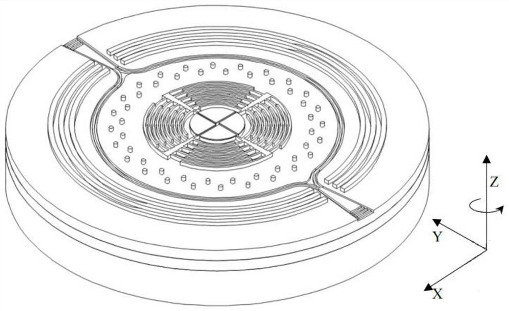
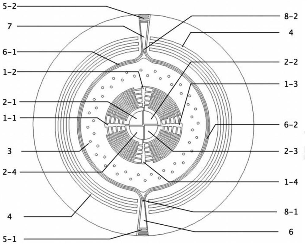
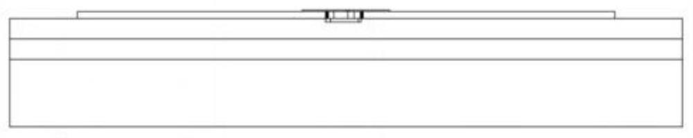
[0041] The substrate material used in the chip-level disc-type acousto-optic standing wave gyroscope in this embodiment is lithium niobate crystal-insulator (LNOI), that is, from top to bottom, it is lithium niobate thin film layer-silicon dioxide crystal layer- Lithium niobate crystal layer, the gyro structure placed on the upper surface of the substrate includes two parts: an acoustic wave drive module and an optical detection module, wherein the acoustic wave drive module is formed by sputtering metal on the surface of the uppermost film layer of the LNOI substrate, and the optical detection module is formed by It is achieved by etching the uppermost thin film layer on the LNOI substrate.

[0042] The thickness of the uppermost film layer of the LNOI substrate is 500nm; in the acoustic wave driving module, the first fork 1-1, the second fork 1-2, the third fork 1-3 and the fourth fork 1-4 are formed The inner radius, outer radius and thickness of the ring-shaped interdigita...


PUM


Abstract

The invention discloses a chip-level disc type acousto-optic standing wave gyroscope which comprises a substrate and a gyroscope structure arranged on the upper surface of the substrate. The base is in a disc shape; the gyroscope structure comprises a sound wave driving module and an optical detection module; the sound wave driving module takes the circle center of the disc as an original point, the sound wave driving module is arranged to be a circle outwards in the radial direction, and the optical detection module is arranged in the middle of the sound wave driving module and is in a circular ring shape; the sound wave driving module comprises an annular interdigital transducer, a metal electrode layer group uniformly sputtered on the annular interdigital transducer, an annular metal dot matrix and an annular reflecting grating which are sequentially arranged from the circle center of the disc to the periphery in the radial direction; the optical detection module comprises a first grating coupler, a light source input end optical waveguide, a first coupler, a second coupler, a signal output end optical waveguide and a second grating coupler which are connected in sequence. The sensitivity of gyroscope detection can be improved.

Description

technical field [0001] The invention relates to the technical field of microsensors, in particular to a chip-level disc-type acousto-optic standing wave gyroscope. Background technique [0002] The gyroscope is a sensor that measures the rotational motion of the carrier relative to the inertial space. It is the core component of applications such as guidance and control, inertial navigation, and motion measurement. It plays an important role in the field of national strategic research. Accuracy is the core index to measure the gyroscope's influence on the performance of the inertial guidance system, and it has become a research hotspot at home and abroad. [0003] At present, MEMS solid-state wave gyroscope has become an international research hotspot because of its fully symmetrical topological characteristic structure, which has the advantages of small size, wide dynamic range, good impact resistance and stability. However, due to the limitations of its existing geometric...

Claims


Application Information

Patent Timeline
Patent Type & Authority Applications(China)
IPC IPC(8): G01C19/5656
CPCG01C19/5656
Inventor 常洪龙田璐申强杨格
Owner NORTHWESTERN POLYTECHNICAL UNIV
Why Eureka
Try Eureka