
A defect location calculation method for ultrasonic detection of weld defects

A defect location and defect technology, applied in the field of pipeline weld defect location calculation, can solve problems such as difficulty in ensuring weld quality inspection, the inability of wedges to fit closely, and the inability of field conditions to meet operating space requirements.

Active Publication Date: 2020-12-11
SHANTOU DONGFANG ULTRASONIC TECH
View PDF6 Cites 0 Cited by
  • Summary
  • Abstract
  • Description
  • Claims
  • Application Information

AI Technical Summary

Problems solved by technology

[0013] c) The height is too large, and the site conditions cannot meet the operating space requirements;
[0014] d) The probe holder is prone to physical collision and jamming with the inner arc of the workpiece;
[0015] e) When the surface curvature of the workpiece is greater than the theoretical curvature, due to the limitation of the adjustable screw, the wedge will not be able to fit tightly with the surface of the workpiece, resulting in poor coupling
[0016] Therefore, operators often have to settle for the next best thing, and only place ultrasonic probes on one side of the welds of heterogeneous structural types of pipes for detection by the method of one side and one side. However, this method is difficult to guarantee the quality of welds and does not meet national standards. Require

Method used


Image

  • A defect location calculation method for ultrasonic detection of weld defects
  • A defect location calculation method for ultrasonic detection of weld defects

Examples


Embodiment Construction

[0049] Further description will be given below in conjunction with the accompanying drawings and preferred embodiments of the present invention.

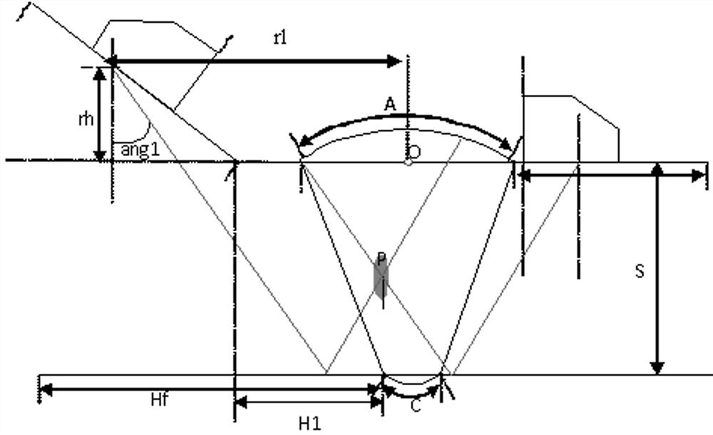
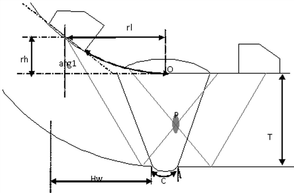
[0050]In this defect position calculation method for ultrasonic detection of weld defects, the two multi-angle ultrasonic probes of the multi-angle bilateral ultrasonic scanning device are respectively placed on both sides of the weld of the pipeline to be tested, and are placed along the circumference of the pipeline to be tested. Conduct equidistant linear scanning to obtain the weld detection data of each sound ray; determine the zero point of the defect, and calculate the vertical distance and horizontal distance of each point of the defect through each weld detection data to obtain the defect position, among which, The vertical distance takes the upper surface of the straight pipe wall as the zero point. When the defect position is below the zero point, it is recorded as a positive value. When the defect position is above the ze...


PUM


Abstract

The invention provides a defect position calculation method for detecting welding seam defects through ultrasounds. The defect position calculation method comprises the following steps: placing two multi-angle ultrasonic probes at two sides of a welding seam of a pipeline to be detected respectively, and carrying out linear scanning at an equal distance along the peripheral direction of the pipeline to be detected to acquire welding seam detection data of each path of sound ray; determining a null point of the defects and calculating a vertical distance and a horizontal distance of each pointof the defect respectively through each welding seam detection data to obtain defect positions. The position of each point of the defects is independently calculated through determining the null pointof the defects of an incident angle of the sound ray according to a linear equation of primary waves and a linear equation of secondary waves. According to the defect position calculation method provided by the invention, the problem that incident starting points and the incident angles of each path of the sound ray of the multi-angle ultrasonic probes are different is solved, and the positions and sizes of the defects in the welding beam are formed only if all the points are combined, so that the welding seam defect defection rate is higher and a result is more intuitive; the quality detection of flange and elbow welding seams is ensured, and the working efficiency and the defect detection capability are greatly improved.

Description

technical field [0001] The invention relates to a method for calculating the position of a weld defect in a pipeline, in particular to a method for calculating the position of a defect in an ultrasonic detection of a weld defect. Background technique [0002] According to the current regulations and standards of my country's petrochemical industry, non-destructive testing is required for welds formed during the installation and repair of oil and gas pipelines to ensure the quality of pipeline welding. [0003] Ultrasonic testing technology has been widely used as the main inspection method in pipeline welding projects in the petrochemical industry because of its simple and fast operation and high sensitivity to the detection of cracks, unfused and other harmful defects. There are a large number of pipe welds of different structural types in petrochemical plants, such as the welds formed between flanges or elbows and straight pipes. According to the national and industry ultr...

Claims


Application Information

Patent Timeline
Patent Type & Authority Patents(China)
IPC IPC(8): G01N29/04
CPCG01N29/04G01N2291/2675
Inventor 李德来陈智发曹燕亮陈宏龙黄数明
Owner SHANTOU DONGFANG ULTRASONIC TECH
Learn More