Device for detecting conductivity of connection position of battery module and detection method of device
A battery module group and detection device technology, applied in the direction of measuring devices, measuring electricity, measuring electrical variables, etc., can solve the problems of small electrical parameters of tiny electronic components, large influence of contact resistance errors, and affecting efficiency, etc., to achieve test results. Persuasive, complete, well-designed effects
- Summary
- Abstract
- Description
- Claims
- Application Information
AI Technical Summary
Problems solved by technology
Method used
Image
Examples
Embodiment 1
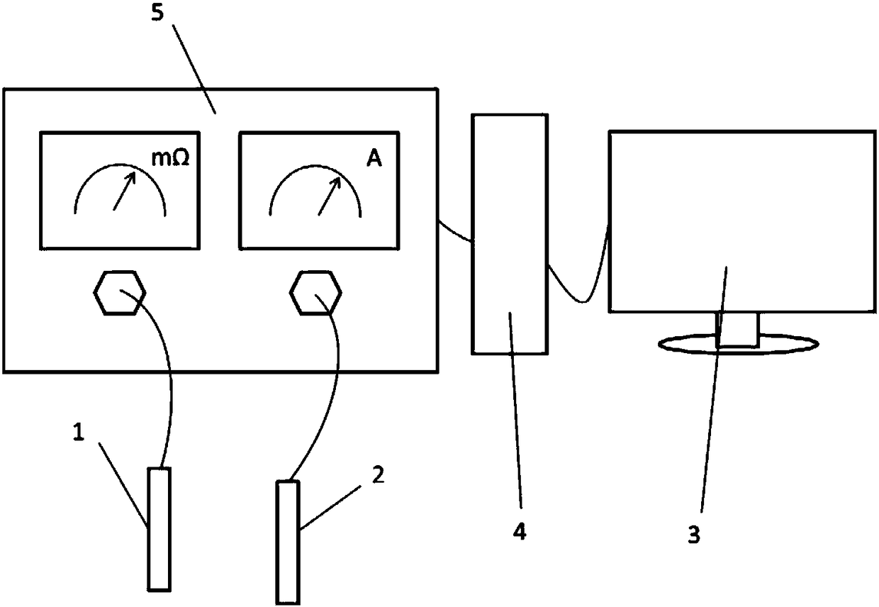
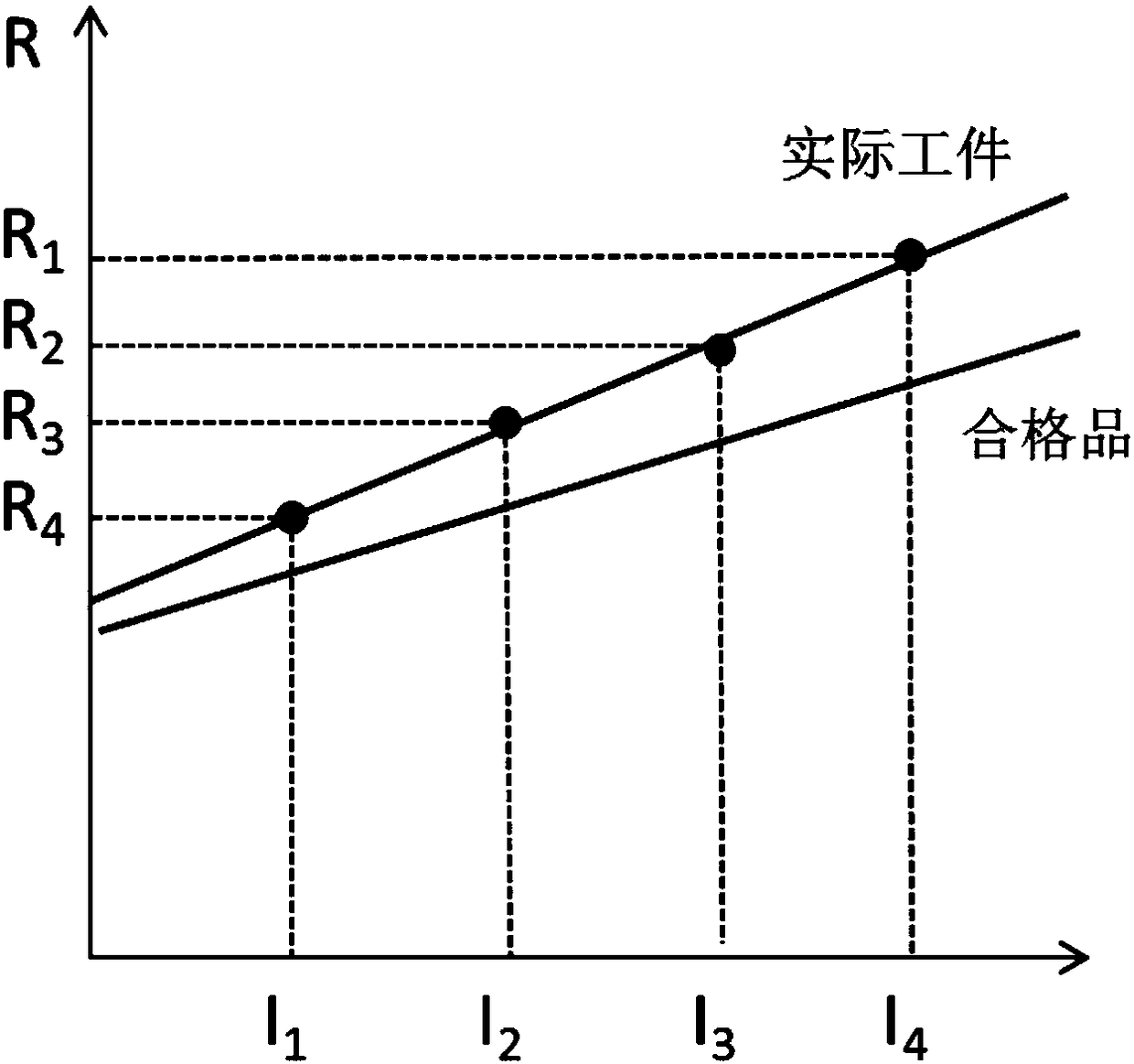
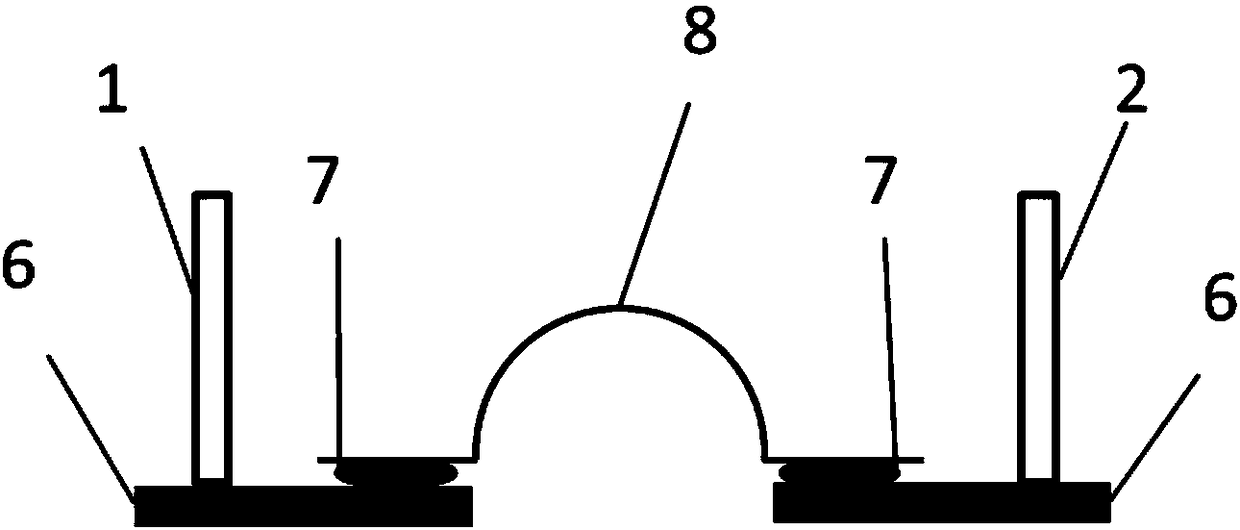
[0037] Such as Figure 1-5 As shown, a detection device and a detection method for continuity at the connection of a battery module group include a tester 5, a computer host 4 and a display 3, and the output end of the tester 5 is electrically connected to the input end of the computer host 4. connected, the output end of the host computer 4 is electrically connected to the input end of the display 3, and the middle part of the tester 5 is embedded with a resistance tester and an electric current tester, and the tester 5 is connected through the wiring knob. The wires are respectively connected to the test positive electrode 1 and the test negative electrode 2, and one end of the test positive electrode 1 and the test negative electrode 2 is connected to the base material 6, and a weld is arranged between two adjacent base materials 6. Seam 7, the welding seam 7 is connected by wire 8, the other end of the test positive electrode 1 and test negative electrode 2 is connected to...
Embodiment 2
[0053] Such as Figure 1-5 As shown, a detection device and a detection method for continuity at the connection of a battery module group include a tester 5, a computer host 4 and a display 3, and the output end of the tester 5 is electrically connected to the input end of the computer host 4. connected, the output end of the host computer 4 is electrically connected to the input end of the display 3, and the middle part of the tester 5 is embedded with a resistance tester and an electric current tester, and the tester 5 is connected through the wiring knob. The wires are respectively connected to the test positive electrode 1 and the test negative electrode 2, and one end of the test positive electrode 1 and the test negative electrode 2 is connected to the base material 6, and a weld is arranged between two adjacent base materials 6. Seam 7, the welding seam 7 is connected by wire 8, the other end of the test positive electrode 1 and test negative electrode 2 is connected to...
Embodiment 3
[0069] Such as Figure 1-5 As shown, a detection device and a detection method for continuity at the connection of a battery module group include a tester 5, a computer host 4 and a display 3, and the output end of the tester 5 is electrically connected to the input end of the computer host 4. connected, the output end of the host computer 4 is electrically connected to the input end of the display 3, and the middle part of the tester 5 is embedded with a resistance tester and an electric current tester, and the tester 5 is connected through the wiring knob. The wires are respectively connected to the test positive electrode 1 and the test negative electrode 2, and one end of the test positive electrode 1 and the test negative electrode 2 is connected to the base material 6, and a weld is arranged between two adjacent base materials 6. Seam 7, the welding seam 7 is connected by wire 8, the other end of the test positive electrode 1 and test negative electrode 2 is connected to...
PUM
 Abstract
Description
Claims
Application Information
 - R&D
- Intellectual Property
- Life Sciences
- Materials
- Tech Scout
- Unparalleled Data Quality
- Higher Quality Content
- 60% Fewer Hallucinations
Browse by: Latest US Patents, China's latest patents, Technical Efficacy Thesaurus, Application Domain, Technology Topic, Popular Technical Reports.
© 2025 PatSnap. All rights reserved.Legal|Privacy policy|Modern Slavery Act Transparency Statement|Sitemap|About US| Contact US: help@patsnap.com


