Channel scanning method for fingerprint recognition

A scanning method and fingerprint recognition technology, applied in character and pattern recognition, acquisition/organization of fingerprints/palmprints, instruments, etc., can solve the problems of affecting the accuracy of fingerprint recognition, and it is difficult to have the same channels, so as to increase the system cost and eliminate the Effects of channel differences, improved accuracy and speed

Inactive Publication Date: 2018-09-14
南京芯思科技有限公司
3 Cites 0 Cited by

AI-Extracted Technical Summary

Problems solved by technology

[0006] However, in the manufacturing process of the image sensor chip, although the design of multiple analog channels is the same, it is difficult to make each channel exactly the same due to the gra...

Abstract

The invention discloses a channel scanning method for fingerprint recognition. The method includes the following steps that: a fingerprint image is scanned through an image scanning sensor; scanned each pixel is connected with a plurality of channels; each pixel is amplified and converted sequentially through each channel, so that the recognition result of each channel can be obtained, wherein therecognition result of the channel has a difference value; the total difference value of each pixel under the plurality of channels is the sum of the difference values of the channels; each pixel is acquired a plurality of times continuously, the product of the number of the times of acquisition and the total difference value is adopted as a pixel difference value; fingerprint image conversion iscarried out on the basis of the pixel difference value, so that a recognition image can be obtained. With the channel scanning method for fingerprint recognition of the invention adopted, differencesbetween the scanning channels can be completely eliminated, and the precision and speed of fingerprint recognition can be improved.

Application Domain

Technology Topic

Fingerprint imagePattern recognition

Image

  • Channel scanning method for fingerprint recognition
  • Channel scanning method for fingerprint recognition
  • Channel scanning method for fingerprint recognition

Examples

  • Experimental program(1)

Example Embodiment

[0025] In order to make the purpose, technical solution and advantages of the present invention clearer, the present invention will be further elaborated below in conjunction with the accompanying drawings.
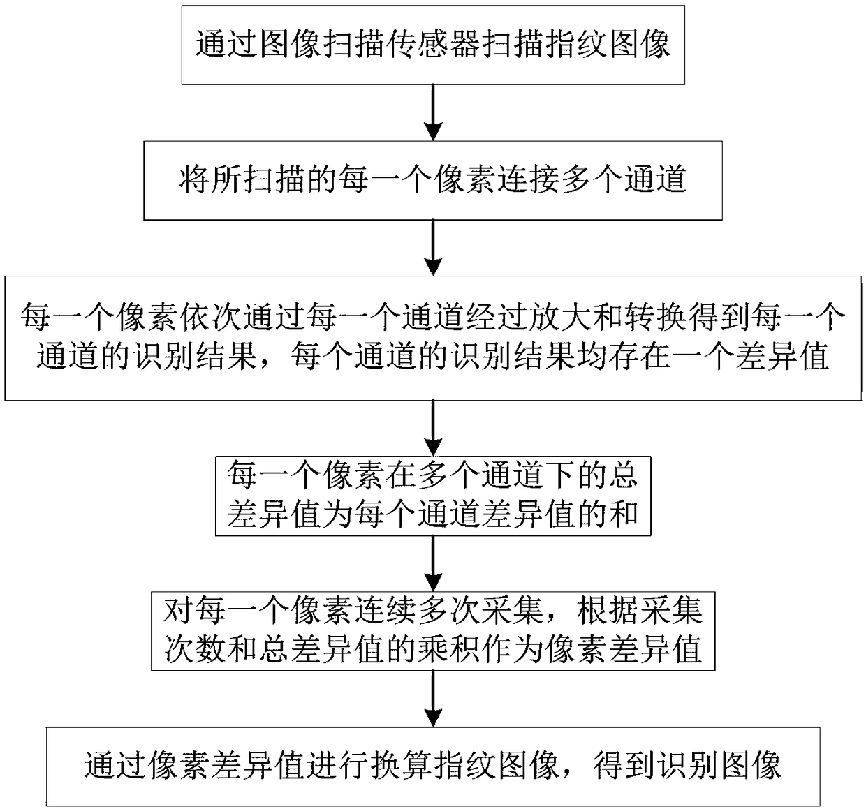
[0026] In this example, see figure 1 As shown, the present invention proposes a kind of channel scanning method for fingerprint identification, comprising steps:
[0027] Scan the fingerprint image through the image scanning sensor;
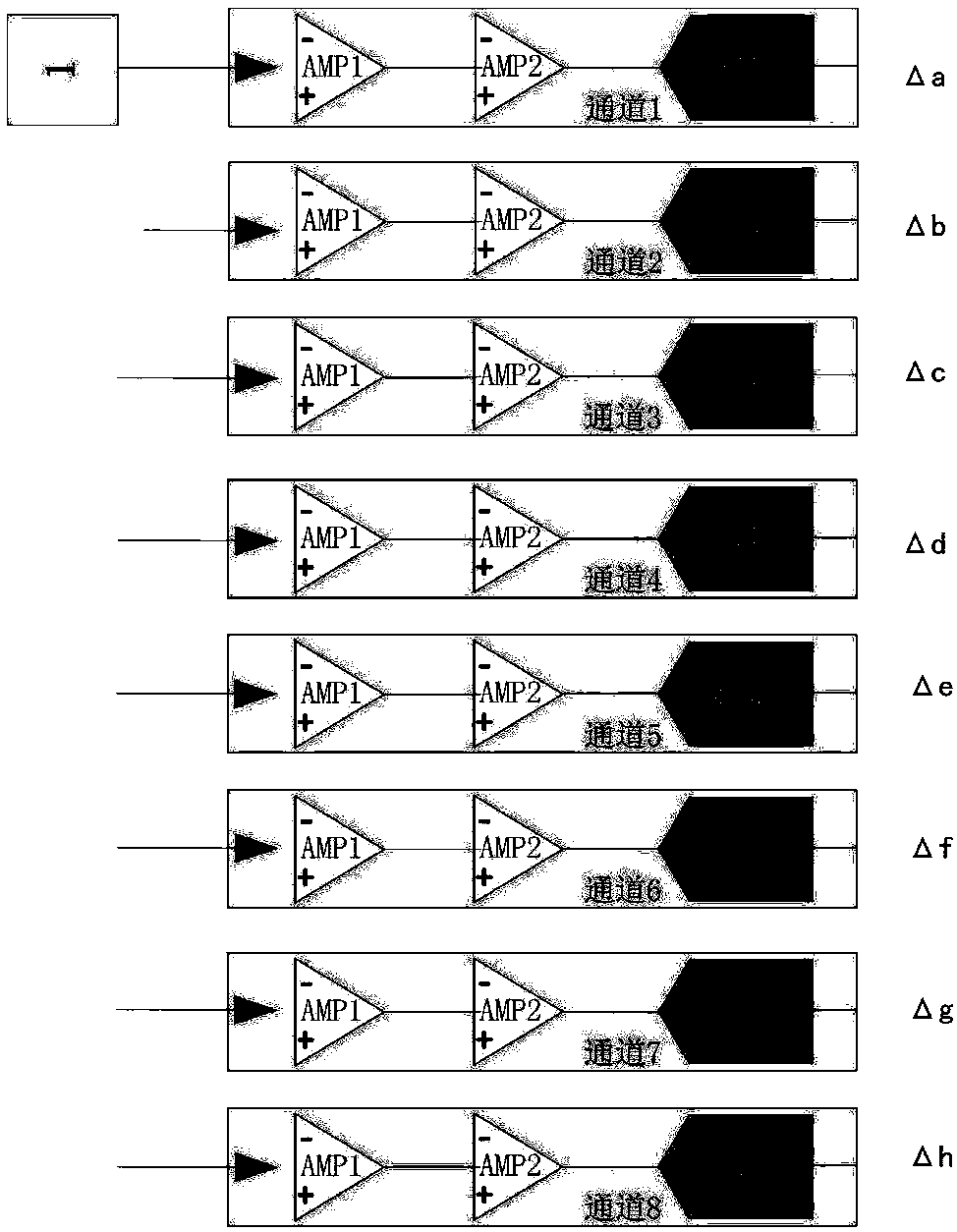
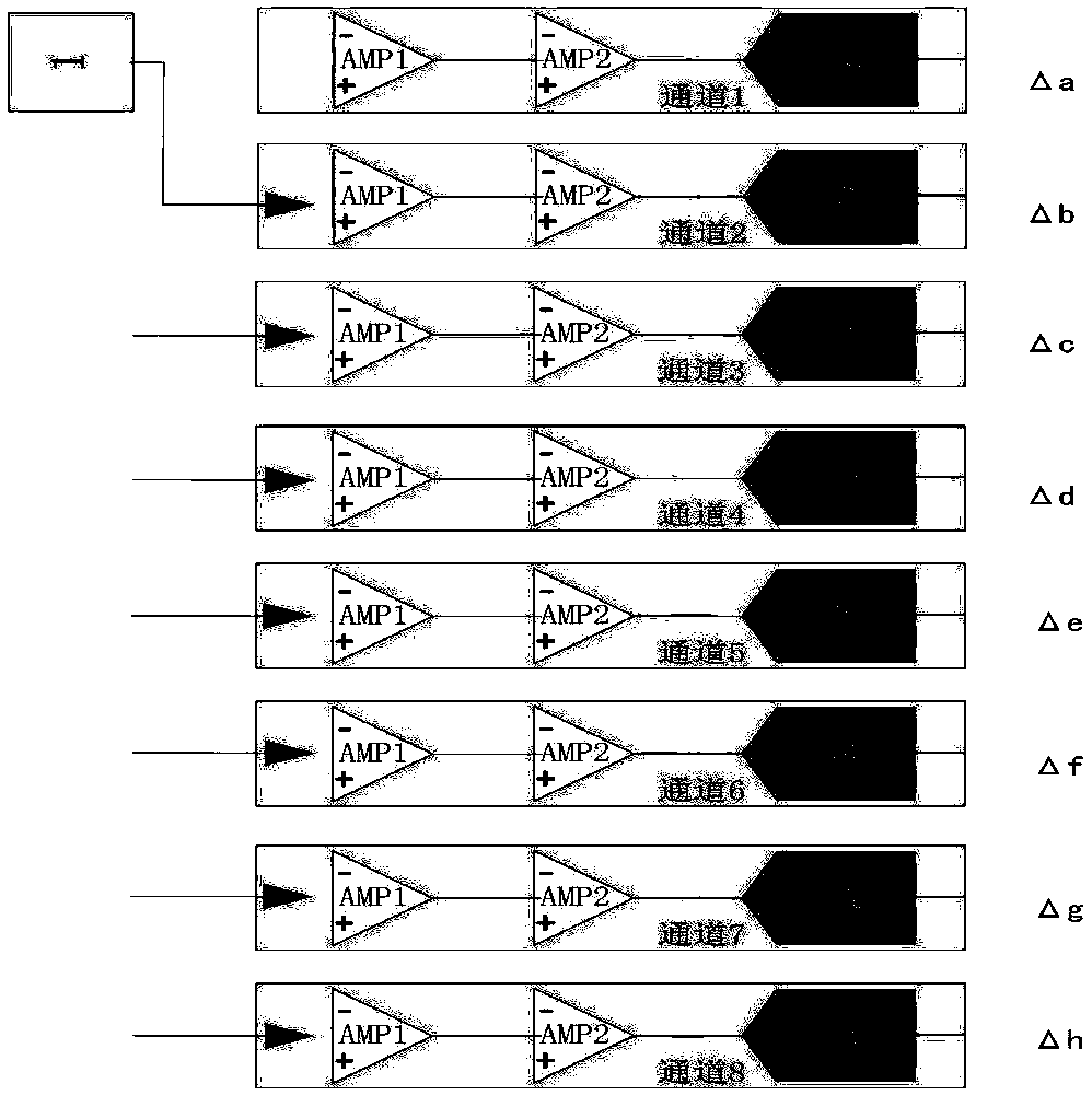
[0028] Connect each scanned pixel to multiple channels;
[0029] Each pixel is amplified and converted through each channel in turn to obtain the recognition result of each channel, and there is a difference value in the recognition result of each channel;
[0030] The total difference value of each pixel under multiple channels is the sum of the difference values ​​of each channel;
[0031] Continuously collect multiple times for each pixel, and use the product of the number of acquisitions and the total difference value as the pixel difference value;
[0032] The fingerprint image is converted by the pixel difference value to obtain the recognition image.
[0033] As an optimization solution of the above embodiment, the number of acquisitions is an integer multiple of the number of channels.
[0034] As an optimization scheme of the above-mentioned embodiment, such as Figure 2-Figure 4 As shown, each pixel of the fingerprint image is connected to 8 channels including channel 1, channel 2, channel 3, channel 4, channel 5, channel 6, channel 7 and channel 8; the difference values ​​for the 8 channels are respectively Δa, Δb, Δc, Δd, Δe, Δf, Δg, and Δh; the number of acquisitions is an integer multiple N of 8 channels, so the pixel difference value is N*(Δa+Δb+Δc+Δd+Δe+Δf+Δg+ Δh).
[0035] As an optimization solution of the above embodiment, the channel includes an amplifier and an analog-to-digital converter, and the scanned pixels are sequentially amplified and converted by the amplifier and the analog-to-digital converter to obtain a recognition result.
[0036] The basic principles and main features of the present invention and the advantages of the present invention have been shown and described above. Those skilled in the industry should understand that the present invention is not limited by the above-mentioned embodiments. What are described in the above-mentioned embodiments and the description only illustrate the principle of the present invention. Without departing from the spirit and scope of the present invention, the present invention will also have Variations and improvements are possible, which fall within the scope of the claimed invention. The protection scope of the present invention is defined by the appended claims and their equivalents.

PUM

no PUM

Description & Claims & Application Information

We can also present the details of the Description, Claims and Application information to help users get a comprehensive understanding of the technical details of the patent, such as background art, summary of invention, brief description of drawings, description of embodiments, and other original content. On the other hand, users can also determine the specific scope of protection of the technology through the list of claims; as well as understand the changes in the life cycle of the technology with the presentation of the patent timeline. Login to view more.

Similar technology patents

Immunochromatography concentration detection method and system based on machine learning

PendingCN112071423AEliminate differencesLittle correlationImage analysisCharacter and pattern recognitionMachine learningImmunochromatographic test
Owner:SHANGHAI JIAO TONG UNIV

Classification and recommendation of technical efficacy words

  • Eliminate differences
  • Improve speed and precision

Method and system for estimating capacity of server

InactiveCN102411515AEliminate differencesAvoid overheadResource allocationSystem serviceRedundancy factor
Owner:STATE GRID CORP OF CHINA +1

Ultra-high resolution pixel electrode arrangement structure signal processing method

InactiveUS20070057190A1Eliminate differencesReduce sensitivity differenceTelevision system detailsTelevision system scanning detailsUltra high resolutionCapacitance
Owner:NAT UNIV SHIZUOKA UNIV

Display device and driving method

ActiveUS20110128259A1Suppressing display unevennessEliminate differencesCathode-ray tube indicatorsDigital storageDisplay deviceControl circuit
Owner:SATURN LICENSING LLC

Inductive coupling plasma device

ActiveCN102573258AEliminates discrepancies in resultsEliminate differencesPlasma techniqueDensity distributionEngineering
Owner:BEIJING NAURA MICROELECTRONICS EQUIP CO LTD
Why Eureka
Try Eureka