LTCC double-layer single-feed circularly polarized microstrip patch array antenna unit

A microstrip patch, array antenna technology, applied in the direction of antenna, antenna array, antenna grounding device, etc., can solve the problem of low profile gain, and achieve the effect of good circular polarization performance, small size and easy processing

Active Publication Date: 2018-09-14
UNIV OF ELECTRONICS SCI & TECH OF CHINA
View PDF5 Cites 18 Cited by
  • Summary
  • Abstract
  • Description
  • Claims
  • Application Information

AI Technical Summary

Problems solved by technology

[0004] The purpose of the present invention is to provide a double-layer single-feed circularly polarized microstrip patch array antenna unit based on LTCC technology to solve the proble

Method used


Image

  • LTCC double-layer single-feed circularly polarized microstrip patch array antenna unit
  • LTCC double-layer single-feed circularly polarized microstrip patch array antenna unit
  • LTCC double-layer single-feed circularly polarized microstrip patch array antenna unit

Examples


Embodiment Construction

[0023] The present invention will be further described in detail below with reference to the drawings and examples, but the embodiments of the present invention are not limited thereto.

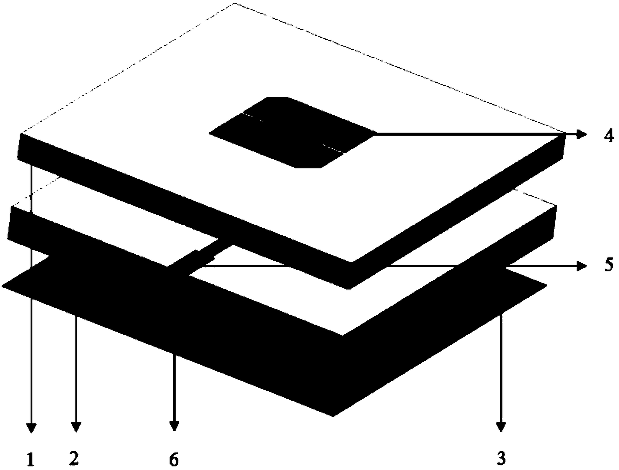
[0024] This embodiment provides a LTCC double-layer single-feed circularly polarized microstrip patch array antenna unit, its structure is as follows figure 1 shown, including:

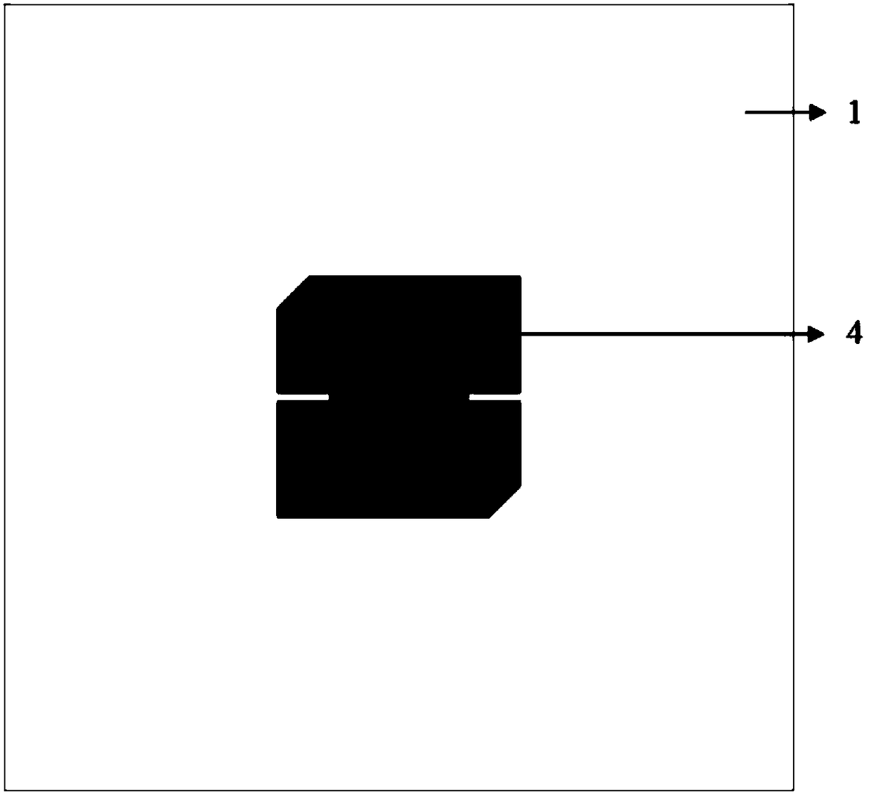
[0025] Upper LTCC substrate 1, such as figure 2 Shown: The substrate is laminated with 11 LTCC cast film sheets with a thickness of 0.1mm and a dielectric constant of 5.9. The lateral dimension of the substrate is 15mm and the vertical dimension is 15mm; Radiating metal patch, the radiating metal patch is located in the center of the upper substrate, with a side length of 4.6mm; the diagonal of the radiating metal patch is cut to achieve circular polarization, and the cut corner is an isosceles right angle with a side length of 0.61mm Triangular, with a rectangular slit with a length of 0.9mm and a width of 0.1mm ...


PUM


Abstract

The invention belongs to the technical field of antenna, and provides an LTCC double-layer single-feed circularly polarized microstrip patch array antenna unit, for solving the contradiction that a current circularly polarized microstrip patch array antenna needs to consider both low profile, circular polarization, high gain, and broadband development. In the LTCC double-layer single-feed circularly polarized microstrip patch array antenna unit, an upper layer of radiation metal patch and a lower layer of radiation metal patch are different in the size; the resonant frequency point of the lower layer of radiation metal patch is higher than the center frequency of the antenna unit; the resonant frequency point of the upper layer of radiation metal patch is lower than the center frequency ofthe antenna unit; the chamfer size of the lower layer of radiation metal patch is greater than the chamfer size of the upper layer of radiation metal patch; and the chamfer size of the upper and lower layers of radiation metal patches enables the single point feed square patch to generate two orthogonal degeneration modes with the same amplitude to form a 90 DEG phase difference. The LTCC double-layer single-feed circularly polarized microstrip patch array antenna unit utilizes the upper and lower radiation metal patches with the same shape and different size, thus being able to preferably consider both the performance demands for low profile and circular polarization of the microstrip patch chip, and greatly improving the frequency band bandwidth of the antenna.

Description

technical field [0001] The invention belongs to the technical field of antennas, and in particular relates to a novel LTCC double-layer single-feed circularly polarized microstrip patch array antenna unit. Background technique [0002] Circularly polarized antennas have orthogonality of rotation, can receive arbitrary polarized waves, and their radiated waves can also be received by arbitrary polarized antennas; when circularly polarized waves are incident on a symmetrical target, the reflected waves will be anti-rotated. Compared with the array radiation antenna unit, the array antenna has higher gain, narrower beam, stronger directivity and spatial beam scanning characteristics. The circularly polarized microstrip patch array antenna not only has the advantages of the above two antennas, but also has the advantages of low microstrip patch antenna profile, simple structure, small size, light weight, easy fabrication, low cost, and can be integrated with the carrier or aircr...

Claims


Application Information

Patent Timeline
IPC IPC(8): H01Q1/38H01Q1/48H01Q1/50H01Q15/24H01Q21/00
CPCH01Q1/38H01Q1/48H01Q1/50H01Q15/24H01Q21/0006H01Q21/0075
Inventor 张怀武吴同庆杨青慧笪策黄鑫甘功雯
Owner UNIV OF ELECTRONICS SCI & TECH OF CHINA
Why Eureka
Try Eureka