
Horizontally polarized omnidirectional antenna with full wave oscillators

A horizontally polarized, omnidirectional antenna technology, applied in the antenna grounding device, the structural connection of the antenna grounding switch, the structural form of the radiating element, etc., can solve the gain drop in the horizontal direction of the pattern, the large difference in the in-band pattern, and the impedance matching. Difficulties and other problems, to achieve the effect of improved horizontal gain, clear principle, and simple feeding design

Pending Publication Date: 2018-09-14
TONGYU COMM INC
View PDF0 Cites 1 Cited by
  • Summary
  • Abstract
  • Description
  • Claims
  • Application Information

AI Technical Summary

Problems solved by technology

However, as the number of vibrators increases, the design of the matching network of the circular array becomes more complex, and impedance matching is difficult. At the same time, the gain in the horizontal direction of the pattern decreases significantly, and the out-of-roundness will also significantly deteriorate. The difference in the pattern within the band is large, and the efficiency It is also greatly reduced; the second method is to increase the electrical length of the oscillator unit in the circular array, such as increasing from half-wavelength to 1 wavelength, the so-called full-wavelength dipole (full-wavelength dipole, L≈ 1.0 · lambda ), its gain can reach G ≈4dBi However, its input impedance is as high as several kΩ, it is extremely difficult to achieve impedance matching, so it has not been applied in engineering

Method used


Image

  • Horizontally polarized omnidirectional antenna with full wave oscillators
  • Horizontally polarized omnidirectional antenna with full wave oscillators
  • Horizontally polarized omnidirectional antenna with full wave oscillators

Examples


Embodiment Construction

[0039] The preferred embodiments of the present invention are given below in conjunction with the accompanying drawings to describe the technical solution of the present invention in detail. Here, the present invention will be described in detail with reference to the accompanying drawings. It should be noted that the preferred implementation examples described here are only used to illustrate and explain the present invention, and are not used to limit or limit the present invention.

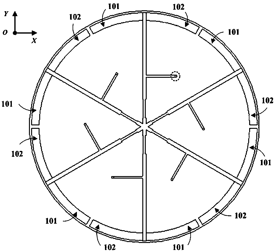
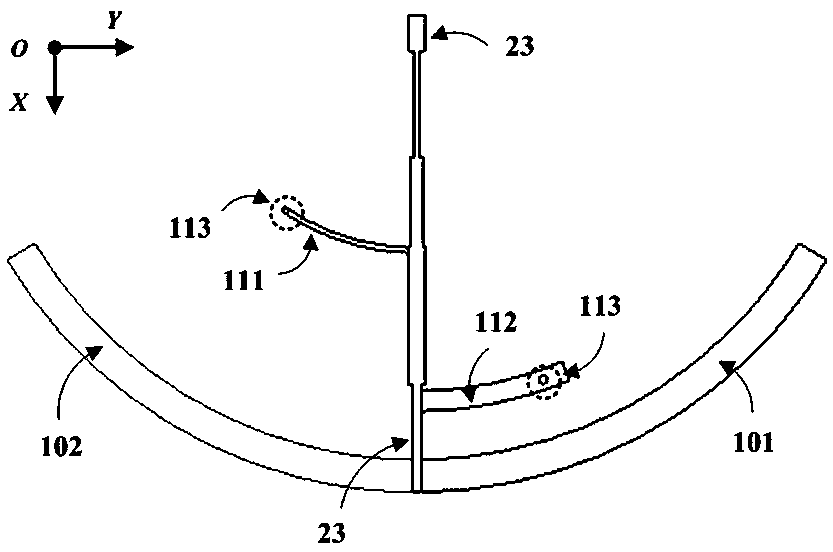
[0040] Full-wave oscillator horizontally polarized omnidirectional antenna, including full-wave oscillator Alford loop antenna, 50Ω coaxial cable feeding the full-wave oscillator Alford loop antenna. The full-wave vibrator horizontally polarized omnidirectional antenna can be stacked with multiple pieces according to needs to increase the gain effect. Compared with the existing horizontally polarized omnidirectional antenna, the omnidirectional antenna with the same number of pieces The full-wa...


PUM


Abstract

Provided is a horizontally polarized omnidirectional antenna with full wave oscillators. Three full wave oscillators are coplanar to form a circular array, a parallel double-conductor feed line is used for feed, the oscillators are connected in parallel equivalently, the array impedance can be reduced greatly, the impedance of a printing feed line is adjusted so that the feed line can match to 50ohm. Breakthrough is made in the technical bottleneck in realizing engineering application due to high impedance, and the structure can be used for design of the vertically as well as horizontally polarized omnidirectional antenna.

Description

technical field [0001] The invention relates to wireless communication antenna equipment and technology, in particular to a full-wave vibrator horizontally polarized omnidirectional antenna. Background technique [0002] Horizontally polarized omnidirectional antenna is an important antenna type in the field of wireless communication, and its application requirements are very strong and extensive. For example, H / V orthogonal dual-polarized omnidirectional MIMO antenna can be combined with vertically polarized omnidirectional antenna to improve communication system capacity. So far, the horizontally polarized horizontal omnidirectional antennas that have been invented are almost all based on the loop antenna theory, that is, the electric small loop antenna and the electric large Alford loop antenna. The former is the earliest horizontally polarized omnidirectional antenna invented, but because the circumference is much smaller than the working wavelength, the current is equa...

Claims


Application Information

Patent Timeline
IPC IPC(8): H01Q1/38H01Q1/48H01Q1/50
CPCH01Q1/38H01Q1/48H01Q1/50
Inventor 李道铁吴中林刘木林
Owner TONGYU COMM INC
Learn More