Heat radiation and diversion cabinet

A cabinet and diversion area technology, applied in cooling/ventilation/heating renovation, electrical components, electrical equipment structural parts, etc., can solve problems such as affecting the appearance of large equipment, occupying communication equipment cabinet space, and reducing the cooling efficiency of the equipment room. , to achieve the effect of improving user perception, saving power and simple structure

Active Publication Date: 2018-09-14
FENGHUO COMM SCI & TECH CO LTD
View PDF3 Cites 1 Cited by
  • Summary
  • Abstract
  • Description
  • Claims
  • Application Information

AI Technical Summary

Problems solved by technology

[0006] 2. The equipment is noisy. The heat dissipation of this kind of air duct equipment mainly depends on increasing the air volume, which leads to the continuous increase of the fan speed, and the noise problem of the equipment is becoming more and more serious. Exceeding the noise will have a negative impact on the staff and even affect the surrounding environment
[0007] 3. The power consumption of the fan is large. As the fan speed increases, the power consumed by the fan is proportional to the cube of the fan speed. When the fan speed is doubled, the power consumed by the fan will increase by 8 times, that is, it takes 8 times the power to exchange 1 times the air volume, the energy efficiency ratio is reduced
[0009] 1. It is inconsistent with the air duct form of the existing machine room. Since the hot air of the equipment is discharged from the bottom and mixed with the cold air blown from the bottom of the machine room, the temperature of the air entering the middle of the equipment will increase and the cooling efficiency of the machine room will be reduced.
[0010] 2. The flow resistance of the system is large, the air enters the upper gap from the middle motherboard panel through the middle motherboard, and then enters the uppermost motherboard to discharge hot air
[0012] 1. Only applicable to 300 deep cabinets, not applicable to 600 deep cabinets, because 600 deep cabinets place equipment back to back, and after one side of the equipment adopts a flow guide device, the hot air discharged from the rear will affect the heat dissipation of the equipment on the other side of the cabinet
[0013] 2. It can only be placed in the gap between equipment and equipment, occupying the space of the communication equipment cabinet
[0014] 3. The device is independent of the equipment and needs to be installed later, which will affect the overall appearance of large equipment

Method used


Image

  • Heat radiation and diversion cabinet
  • Heat radiation and diversion cabinet
  • Heat radiation and diversion cabinet

Examples


Embodiment 1

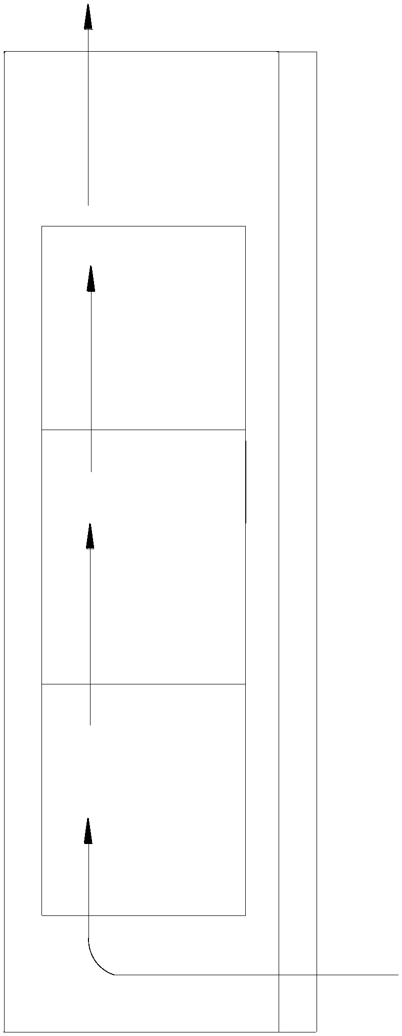
[0040] Embodiment one, see Figure 1 to Figure 6 As shown, the embodiment of the present invention provides a heat dissipation guide cabinet, including:

[0041] Cabinet 1, the inside of the cabinet 1 is provided with a multi-layer main board 10, the cabinet 1 is also provided with a first air duct 4 and a second air duct 5, and the first air duct 4 includes a The first air inlet 11, and the first air outlet 13 arranged in the middle of the cabinet 1, the second air duct 5 includes the second air inlet 14 arranged in the middle of the cabinet 1, and the second air inlet 14 arranged in the top of the cabinet 1 The second air outlet 12, the first air outlet 13 and the second air inlet 14 are arranged perpendicular to the panel of the cabinet body 1;

[0042] The partition 3 installed between the panel of the cabinet body 1 and the main board 10 , the partition 3 is arranged between the first air outlet 13 and the second air inlet 14 .

[0043]The heat dissipation guide cabinet...

Embodiment 2

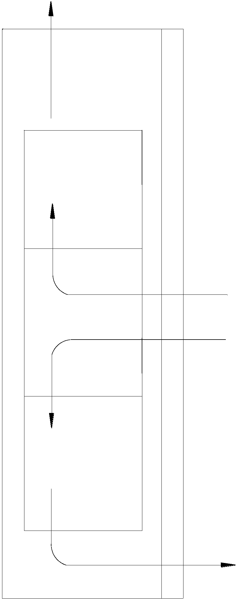
[0044] Embodiment two, on the basis of the technical solution of embodiment one, refer to Figure 1 to Figure 6 As shown, the heat dissipation guide cabinet also includes a guide device 2 arranged between the middle motherboards 10 in the cabinet body 1, and the guide device 2 includes a first guide area 21 and a second guide area 22. The first air guide area 21 is set on the first air channel 4, and the second air guide area 22 is set on the second air channel 5; by setting the air guide device 2 to guide the cold air circulation, Wherein the first guide area 21 is arranged on the first air channel 4, guides the cold air to enter from the first air inlet 11, after passing through the lower area of ​​the lower main board 10 and the middle main board 10, the heat therein is taken out, and the first outlet The air port 13 is discharged; the second guide area 22 is arranged on the second air duct 5, and the cold air is guided to enter from the second air inlet 14, and after passi...

Embodiment 3

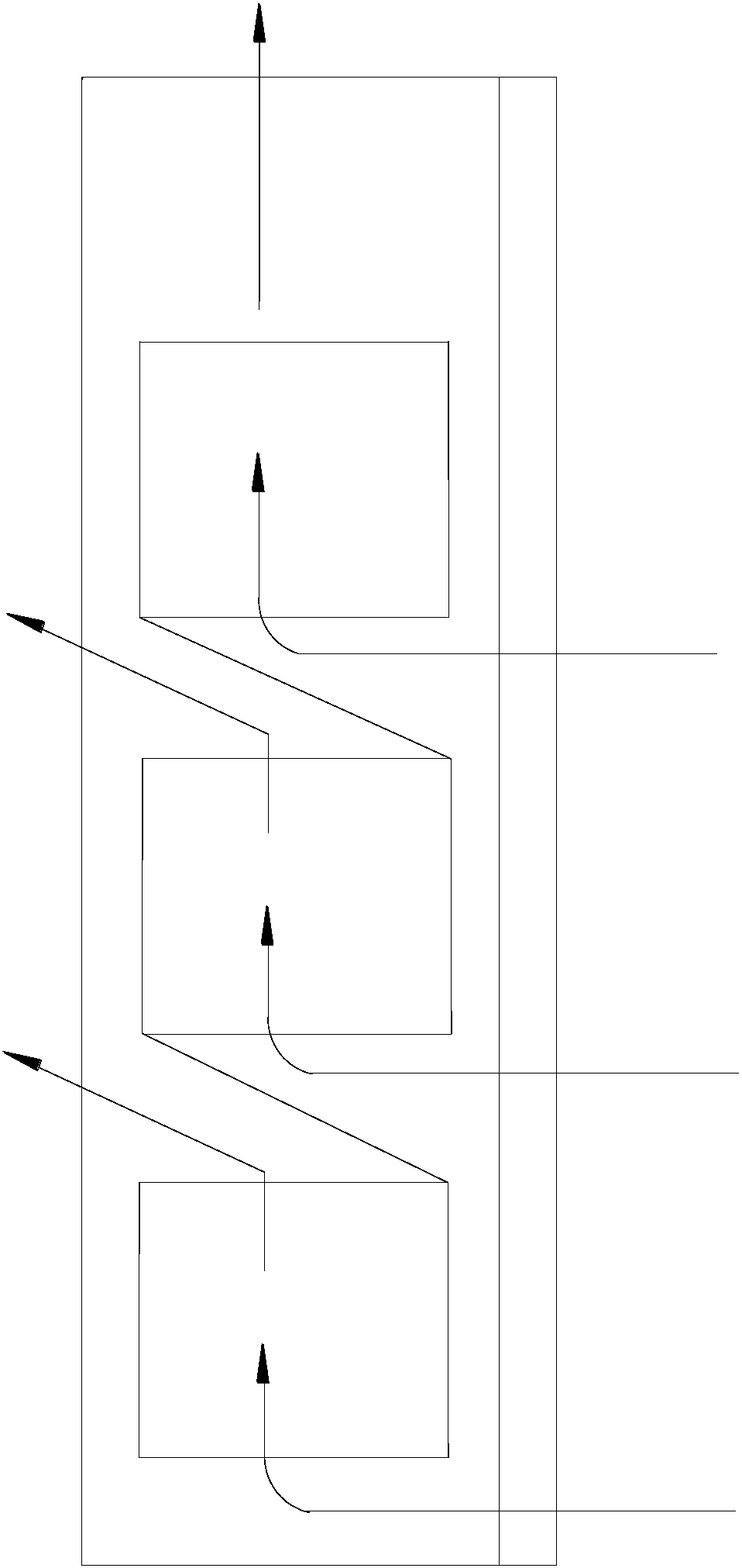
[0045] Embodiment three, on the basis of the technical scheme of embodiment two, see Figure 1 to Figure 6 As shown, the deflector 2 includes a mounting base 20, one side of the mounting base 20 is a first deflecting area 21, and the other side is a second deflecting area 22; using the mounting base 20 is convenient for the deflecting device 2 The division of the upper diversion area and the setting of each component.


PUM


Abstract

The invention discloses a heat radiation and diversion cabinet comprising a cabinet body which is internally provided with a first air duct and a second air duct. The first air duct comprises a firstair inlet which is arranged on the bottom part of the cabinet body and a first air outlet which is arranged in the middle part of the cabinet body. The second air duct comprises a second air inlet which is arranged in the middle part of the cabinet body and a second air outlet which is arranged on the top part of the cabinet body. The first air outlet and the second air inlet are perpendicular tothe cabinet body panel. The heat radiation and diversion cabinet also comprises a separating plate which is installed between the cabinet body panel and the mainboard. The separating plate is arrangedon the position between the first air outlet and the second air inlet. Cold air intaking and hot air discharging can be independently performed, two sets of air ducts have no mutual interference andthe air temperature superposition effect does not occur so that the heat radiation effect is great; besides, the system flow resistance is low so that the rotating speed of the equipment fan can be reduced, the electric energy consumed for high speed rotation of the fan can be saved, and the comprehensive effect of energy conservation and emission reduction can be achieved.

Description

technical field [0001] The invention relates to the field of heat dissipation devices for electronic equipment, in particular to a heat dissipation guide cabinet. Background technique [0002] At present, for large-scale communication equipment, the power consumption of the motherboard in the cabinet is increasing, and the number of motherboards is also increasing. With the increasing heat flux density of the motherboard of large-scale equipment, the uppermost motherboard is in a high-temperature environment for a long time, and the heat on the motherboard is sensitive. There is a risk of overheating of the device temperature, which will shorten the life of the core device, accelerate aging, and even damage the device and the main board, resulting in the failure of the device or the main board to operate normally. [0003] For the heat dissipation inside the large-scale communication equipment cabinet, the existing technology usually adopts the following air duct solutions: ...

Claims


Application Information

Patent Timeline
IPC IPC(8): H05K7/20
CPCH05K7/20554
Inventor 金漫丽李梦君
Owner FENGHUO COMM SCI & TECH CO LTD
Why Eureka
Try Eureka