Tea cup production line, and method for producing tea cup by using production line

A production line and tea cup technology, applied in the field of tea cup production lines, can solve the problems of poor operation regulation, troublesome cleaning, affecting the uniform effect of glazing, etc., and achieve the effect of improving the utilization rate and reducing waste.

Active Publication Date: 2018-09-18
福建省东丰阁文化发展有限公司
View PDF8 Cites 0 Cited by
  • Summary
  • Abstract
  • Description
  • Claims
  • Application Information

AI Technical Summary

Problems solved by technology

But this type of invention has the following deficiencies: First, the way of spraying is difficult to ensure the uniformity of the oil surface as a whole, especially for the belly with concave-convex structure and multi-arc structure, it is easy to produce glaze ripples and unstable glaze film; Second, the material ejected from the spray gun will cause the problem of splashing everywhere, which will bring great trouble to the subsequent cleaning; for example, the glazing device for the outer surface of a ceramic cup disclosed in patent application 201510304005.8 also adopts the method of spraying and glazing. Compared with the above invention, the technical solution of the invention is different in that the overall glazing device is limited in the glaze spray cover, and the problem of glaze water splashing is avoided through the sealing and blocking functions of the spray glaze cover
However, the glaze water sprayed onto the spray glazing cover may bounce back and fall onto the cup embryo, which affects the uniform effect of glazing; in addition, the operation and regulation of the sealed glazing method is poor; On the calyx embryo, the binding effect between it and the calyx embryo needs to be improved

Method used


Image

  • Tea cup production line, and method for producing tea cup by using production line
  • Tea cup production line, and method for producing tea cup by using production line
  • Tea cup production line, and method for producing tea cup by using production line

Examples


Embodiment 1

[0054] Such as figure 1 As shown, this embodiment discloses a production line for tea cups, which includes a embryo making mechanism, a glazing mechanism, and a glaze firing kiln in sequence from front to back according to the technological process.

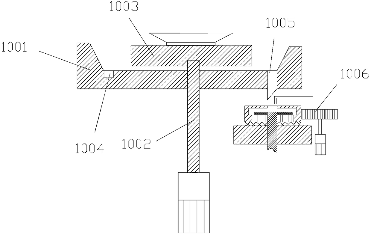
[0055] Such as Figure 2-4 As shown, the embryo-making mechanism includes a embryo-making table 1001, a embryo-making rotating shaft 1002, and a embryo-making turntable 1003. The edge of the upper surface of the embryo-making table 1001 extends upwards to form a wide-mouth structure. The embryo-making turntable 1003 is located in the cavity of the wide-mouth structure and is rotatably connected with the embryo-making table 1001 through the embryo-making rotating shaft 1002 . There is also a spiral guide groove 1004 on the embryo making table 1001, the thickness of the side wall of the guide groove 1004 gradually increases from its feed inlet to its discharge outlet 1005 and the discharge outlet 1005 communicates with the outside...

Embodiment 2

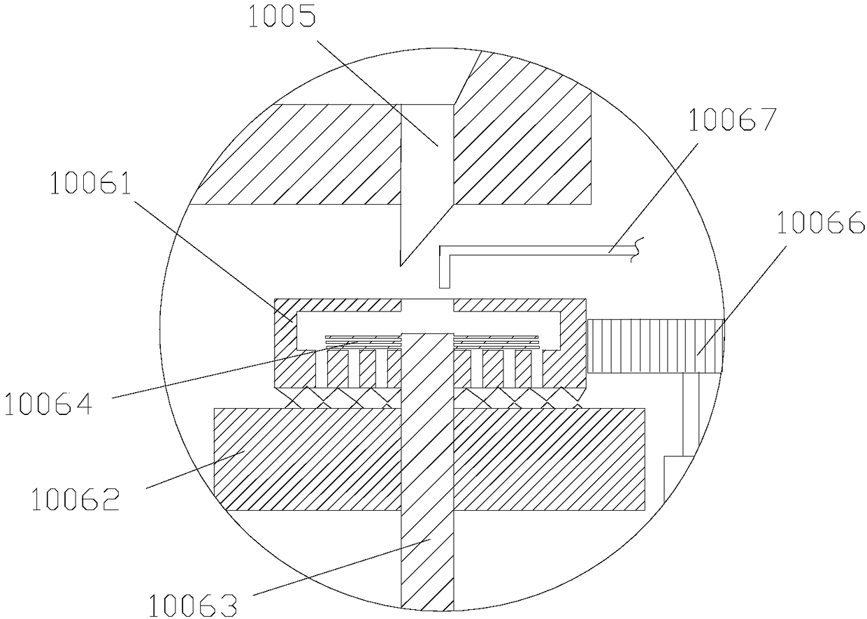
[0063] Such as Figure 2-3As shown, the difference between this embodiment and the above-mentioned embodiments is that the abrasive device 1006 includes an upper rotating grinding disc 10061 and a lower fixed grinding disc 10062, and the upper rotating grinding disc 10061 is located above the lower fixed grinding disc 10062 and is rotatably connected to the lower fixed grinding disc 10062 through the grinding disc rotating shaft 10063. . The top of the upper rotating millstone 10061 is provided with an upper rotating millstone 10061 feed port, and the bottom of the upper rotating millstone 10061 is provided with a plurality of upper rotating millstones 10061 feeding ports, and the upper rotating millstone 10061 feeding port is connected with a plurality of upper rotating millstones 10061 for discharging. The mouths are connected. Stirring impellers 10064 are provided on a section of the grinding disc rotating shaft 10063 extending into the inner cavity of the upper rotating g...

Embodiment 3

[0068] Such as Figure 7 , 10 , 11, the difference between this embodiment and the above embodiments is that the auxiliary intermittent lifting mechanism 113 includes an auxiliary fixing seat 1131 , an auxiliary lifting slider 1132 , and an auxiliary incomplete gear 1133 . The auxiliary lifting slider 1132 is L-shaped, including an auxiliary vertical section 11321 and an auxiliary horizontal section 11322 . The auxiliary elastic device 114 , the auxiliary intermittent push-out mechanism 115 , and the auxiliary clamping device 116 are all arranged on the auxiliary horizontal section 11322 .

[0069] Such as Figure 10 , 11 As shown, the auxiliary vertical section 11321 is slidingly matched with the auxiliary fixing seat 1131. Specifically, the auxiliary gear teeth 1134 may be rotatably connected to the auxiliary fixing seat 1131, and the side of the auxiliary vertical section 11321 is provided with a part meshing with the auxiliary gear teeth 1134. The auxiliary sawtooth ba...


PUM


Abstract

The invention discloses a tea cup production line sequentially comprising a blank making mechanism, a glazing mechanism, a glost kiln and an auxiliary glazing device from front to back according to aprocess flow. The blank making mechanism comprises a blank making table, a blank making rotary shaft and a blank making rotary plate; a circle of guiding chute is further formed in the blank making table; a grinding device is arranged under a discharge hole of the guiding chute; the glazing mechanism comprises a main rotary base and a hairbrush; a cup blank to be glazed is arranged on the main rotary base; the main rotary base rotates to drive the cup blank to be glazed to rotate; a bristle end of the hairbrush can be in abut-joint to the outer surface of the cup blank to be glazed; and the auxiliary glazing device comprises an auxiliary rotary base, a black glaze cup model, an auxiliary contact rod, an auxiliary batch type lifting mechanism, an auxiliary elastic device, an auxiliary batchtype pushing mechanism and an auxiliary clamping device. The invention further discloses a method for producing a tea cup by using the tea cup production line. The tea cup production line provided bythe invention has the advantages of high pug utilization rate, uniformity in glazing, and good glazing effect.

Description

technical field [0001] The invention relates to the technical field of ceramic technology, in particular to a production line for tea cups and a method for producing tea cups using the production line. Background technique [0002] Ceramics include pottery and porcelain, which refer to products made of plastic porcelain clay and porcelain stone ore, glazed with feldspar and quartz, and formed, dried, and fired, mainly for daily use, art, and architectural pottery. As a kind of ceramic products, cups refer to daily utensils that hold liquids, and the materials are usually ceramics, wood, bamboo, metal, etc. Commonly used items such as tea cups, oil cups, and lamp cups. The preparation process of the cup usually includes the following steps: embryo drawing, trimming, drying of the mud embryo, glazing of the embryo, entering the kiln for firing, building the cup and exiting the kiln, etc. [0003] The embryo drawing and embryo repairing of the prior art are all completed on ...

Claims


Application Information

Patent Timeline
Patent Type & Authority Applications(China)
IPC IPC(8): B28B11/04B28B11/24B28B1/02
CPCB28B1/02B28B11/044B28B11/046B28B11/243
Inventor 周辉黄建
Owner 福建省东丰阁文化发展有限公司
Why Eureka
Try Eureka