A permeable asphalt concrete structure and its construction method

A technology of permeable concrete and concrete structure, which is applied to the coagulation pavement, roads, buildings and other directions of on-site paving, can solve the problems of not being able to effectively remove road moisture, icing, road slippery, etc. Penetration effect, the effect of increasing the air-drying area

Inactive Publication Date: 2020-05-12
HUANGHUAI UNIV +1
View PDF5 Cites 0 Cited by
  • Summary
  • Abstract
  • Description
  • Claims
  • Application Information

AI Technical Summary

Problems solved by technology

[0004] Aiming at the deficiencies of the prior art, the present invention provides a permeable asphalt concrete structure and its construction method, which solves the problem that in the prior art, there is no structure capable of effectively removing moisture from the pavement during the rainy season and continuous rainy weather, and there are still roads that cause road damage. Slippery and icy issues

Method used


Image

  • A permeable asphalt concrete structure and its construction method
  • A permeable asphalt concrete structure and its construction method
  • A permeable asphalt concrete structure and its construction method

Examples


Embodiment 1

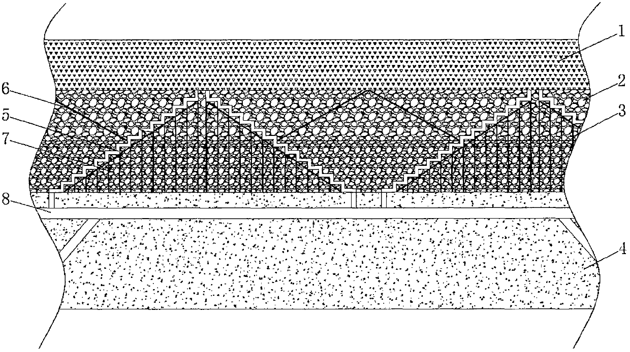
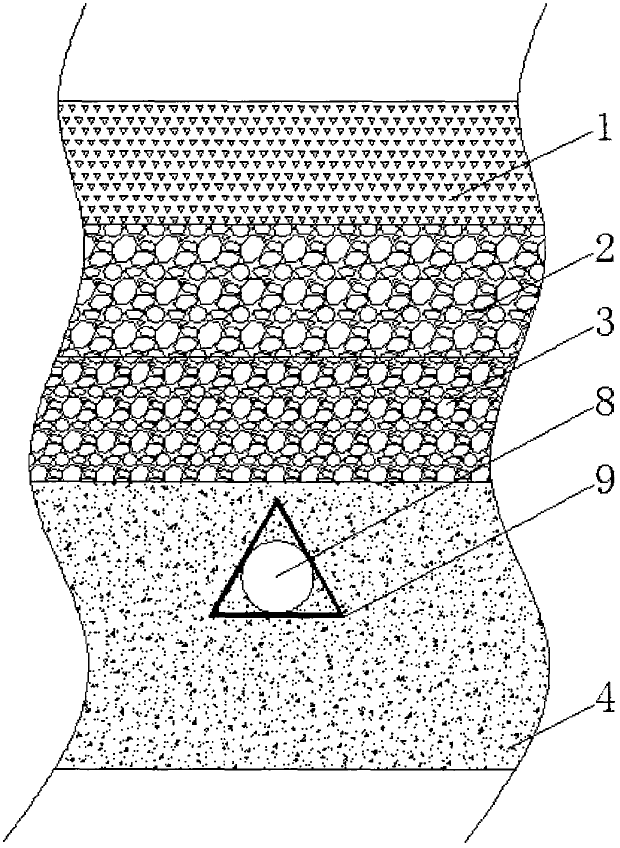
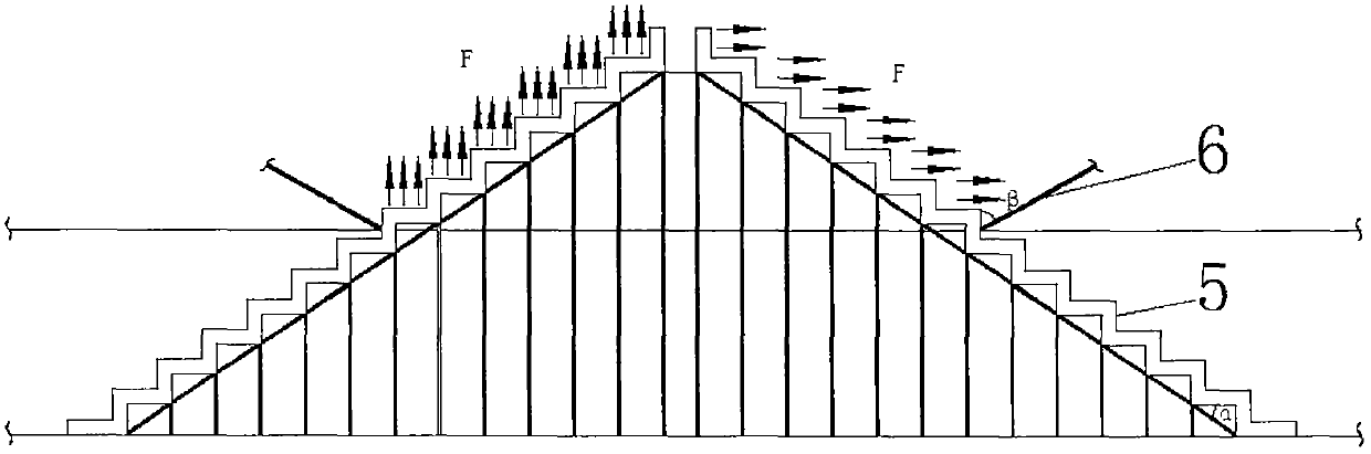
[0034] Such as Figure 1-2 Shown, a kind of permeable asphalt concrete structure, comprises asphalt permeable concrete layer 1 and cement permeable concrete layer 3, is laid with a layer of airflow divergence layer 2 between asphalt permeable concrete layer 1 and cement permeable concrete layer 3, cement permeable concrete layer 3 A layer of air-drying air-drying layer 4 is laid on the bottom, and several groups of stepped air-diffusing ducts 5 are arranged horizontally and linearly in the air-diffusing layer 2, and the stepped air-diffusing ducts 5 extend into the cement permeable concrete layer 3 and are in contact with the air-drying air-drying layer 4 , the left and right sides of each set of stepped air-diffusing ducts 5 in the air-flow diverging layer 2 are in contact with the air guide plates 6, and the adjacent two sets of air guide plates 6 form a triangle with the cement permeable concrete layer 3, and each set The right angles at the bottom of the stepped air-disper...

Embodiment 2

[0036] On the basis of Example 1, such as image 3 As shown, the air guide direction of the air guide plate 6 is based on the plane of the cross section, and the air guide area is based on the area of ​​the air guide plate 6 . Preferably: the included angle between the air guide plate 6 and the direct contact side of the stepped air diffuser duct 5 is 60°-80° based on the plane of the cross section.

Embodiment 3

[0038] On the basis of Examples 1 and 2, such as image 3 As shown, the individual channel surfaces of the stepped air diffusion ducts 5 in the air distribution layer 2 are all provided with wide openings, and the air flow direction formed by the wide openings is consistent with the air guide direction of the air guide plate 6 .


PUM


Abstract

The invention relates to the technical field of road engineering and discloses a pervious asphalt concrete structure. The pervious asphalt concrete structure comprises a pervious asphalt concrete layer and a pervious cement concrete layer; an airflow dispersion layer is laid between the pervious asphalt concrete layer and the pervious cement concrete layer; an airflow air drying layer is laid at the bottom of the pervious cement concrete layer; a plurality of groups of step type air dispersion pipelines are arranged in the airflow dispersion layer in the transverse direction in the form of a straight line; the step type air dispersion pipelines extend into the pervious cement concrete layer to be in contact with the airflow air drying layer; air guide plates are in contact with both left and right edges of each group of step type air dispersion pipelines in the airflow dispersion layer; and the two adjacent groups of air guide plates form a triangle together with the pervious cement concrete layer. According to the pervious asphalt concrete structure, the problem that roads are slippery and icy because water on pavements cannot be effectively removed in rainy seasons and continuouscloudy and rainy weathers in the prior art is solved; the pavements can be rapidly air-dried to avoid slipping of pedestrians and vehicles so that traffic accidents are avoided.

Description

technical field [0001] The invention relates to the technical field of road engineering, in particular to an air-dried pavement permeable asphalt concrete structure and a construction method thereof. Background technique [0002] In the continuous rainy season or winter continuous rainy weather, because the rain on the road is difficult to drain continuously, the road will be slippery or icy, which will increase the difficulty of driving, which is not conducive to the passage of pedestrians and vehicles, and will seriously cause traffic accidents. In the patent CN103233410A, a permeable asphalt cement concrete ground structure with heating function is disclosed, which dehumidifies and melts snow by using solar energy storage to generate heat, but in continuous rainy seasons or continuous rainy weather in winter, solar energy cannot supply power normally , the heating function fails, the road is slippery or icy, and in the existing road engineering, there is no structure that...

Claims


Application Information

Patent Timeline
Patent Type & Authority Patents(China)
IPC IPC(8): E01C7/32
CPCE01C7/32
Inventor 张启志范继涛李庆庆田永飞程险峰苑晶吕二文范元朝苗继承刘新华
Owner HUANGHUAI UNIV
Why Eureka
Try Eureka