A method for measuring the pressure of an excitable gas pressure vessel

A technology of gas pressure and measurement method, which is applied in the direction of fluid pressure measurement, heat measurement, and measurement device using acoustic methods. It can solve the problems of unsuitable for on-site gas detection, long response time, and complex implementation, and achieve stable work and composition. Simple, low-cost effects

Active Publication Date: 2020-06-12
武汉映瑞电力科技有限公司
View PDF6 Cites 0 Cited by
  • Summary
  • Abstract
  • Description
  • Claims
  • Application Information

AI Technical Summary

Problems solved by technology

[0008] In order to solve the deficiencies in the prior art, the present invention provides an excitable gas pressure vessel pressure measurement method, which solves the problems of high cost, complex implementation, and long response time that are not suitable for on-site gas detection in the traditional gas pressure vessel pressure measurement method. The problem

Method used


Image

  • A method for measuring the pressure of an excitable gas pressure vessel
  • A method for measuring the pressure of an excitable gas pressure vessel
  • A method for measuring the pressure of an excitable gas pressure vessel

Examples


Embodiment

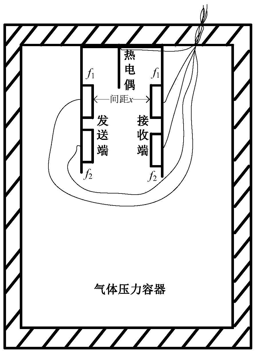
[0055] Assume that 98% CH is stored in the gas pressure vessel 4 -2%N 2 natural gas, the frequencies of the two pairs of ultrasonic probes are f 1 = 40kHz and f 2 = 125kHz.

example 1

[0056] Example 1 (positive pressure environment, assuming 10atm):

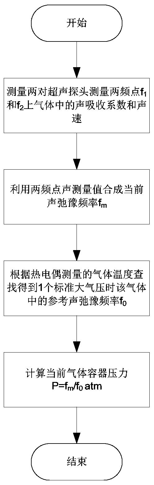
[0057] 1) Under the current pressure environment, two pairs of ultrasonic probes respectively measure two frequency points f 1 = 40kHz and f 2 = 125kHz;

[0058] 2) Obtain the sound absorption coefficient α(f 1 ) = 0.191m -1 , α(f 2 ) = 1.846m -1 and the speed of sound c(f 1 )=443.7m / s, c(f 2 ) = 443.8m / s;

[0059] 3) Using the acoustic relaxation frequency synthesis algorithm of two-frequency point acoustic measurement values ​​can be calculated as follows:

[0060]

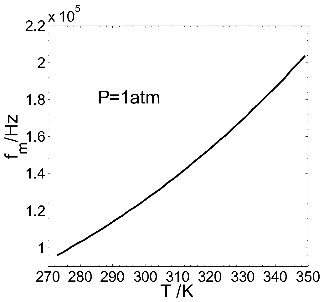
[0061] 4) The gas temperature T measured by a thermocouple is 295K; image 3 is 2%N 2 -98%CH 4 Under 1 standard atmospheric pressure (1atm=101.325kPa), the curve of the acoustic relaxation frequency value when the temperature is 270K~350K, the acoustic relaxation frequency f 0 =1.190×10 5 Hz;

[0062] 5) f obtained by m and f 0 The gas container pressure P=f can be calculated m / f 0 ≈10atm.

example 2

[0063] Example 2 (positive pressure environment, different from the chamber pressure in Example 1, assumed to be 5atm):

[0064] 1) Under the current pressure environment, two pairs of ultrasonic probes respectively measure two frequency points f 1 = 40kHz and f 2 =125kHz

[0065] 2) Obtain the sound absorption coefficient α(f 1 ) = 0.3806m -1 , α(f 2 ) = 3.573m -1 and the speed of sound c(f 1 )=443.8 m / s, c(f 2 ) = 443.9m / s;

[0066] 3) The combination algorithm of two-frequency point acoustic measurement values ​​using the acoustic relaxation frequency can be calculated to obtain

[0067]

[0068]4) The temperature T of the gas measured by a thermocouple is 295K; by image 3 By looking up the table, we know that when the temperature T is 295K, the acoustic relaxation frequency f 0 =1.190×10 5 Hz;

[0069] 5) f obtained by m and f 0 The gas container pressure P=f can be calculated m / f 0 ≈5 atm.


PUM


Abstract

The invention discloses a method for measuring the pressure intensity of an excitable gas (diatomic or polyatomic molecular gases, such as natural gas, carbon dioxide, chlorine) pressure vessel. The method comprises the following steps: placing two ultrasonic probes with frequencies f1 and f2 and a thermocouple in the gas pressure vessel, and obtaining the measurement values of acoustic absorptioncoefficients alpha(f1) and alpha(f2) on two selected frequency points f1 and f2 and measurement values of sound speeds c(f1) and c(f2) through the two ultrasonic probes, wherein the measurement values are used for the synthesis of the acoustic relaxation frequency fm of the gas; measuring the current gas temperature measured through the thermocouple, measuring the gas reference acoustic relaxation frequency f0 when the current gas temperature is measured to be 1 standard atmospheric pressure (i.e., 1 atm = 101.325 kPa) in a manner of table look-up; and obtaining the pressure intensity of thegas vessel through the synthesized acoustic relaxation frequency fm and the reference acoustic relaxation frequency f0. The method is advantageous in online detection, lossless detection, quick response, miniature low power consumption, simple composition, stable long-time operation, and high measurement precision.

Description

technical field [0001] The invention relates to the field of pressure monitoring in a gas pressure vessel, in particular to a method for measuring the pressure of an excitable gas pressure vessel. Background technique [0002] An important thermal parameter of gas pressure vessels is pressure (also known as pressure in industrial measurement). On the one hand, many processes require a specific pressure to achieve the desired effect, and it is necessary to obtain an accurate value of the container pressure; on the other hand, in order to improve production efficiency, many chemical reactions need to be carried out under high pressure, monitoring and controlling the pressure in the gas pressure vessel It is an important link in the whole production process; third, some operational errors or violent and abnormal chemical reactions in the production and transportation process will cause the pressure inside the container to rise rapidly. In order to prevent damage to the pressure...

Claims


Application Information

Patent Timeline
Patent Type & Authority Patents(China)
IPC IPC(8): G01L11/06G01K7/02
CPCG01K7/02G01L11/06
Inventor 张克声李岩
Owner 武汉映瑞电力科技有限公司
Why Eureka
Try Eureka