Fatigue-crack propagation monitoring system based on microstrip antenna sensor and monitoring method thereof

A technology of fatigue crack growth and microstrip antenna, which is applied in the field of fatigue crack growth monitoring system, can solve the problems of high cost, unintuitive, long detection period, etc., and achieve the effect of low cost and simple production

Inactive Publication Date: 2018-09-18
WUHAN UNIV OF TECH
View PDF6 Cites 9 Cited by
  • Summary
  • Abstract
  • Description
  • Claims
  • Application Information

AI Technical Summary

Problems solved by technology

However, these methods have relatively obvious defects. Ultrasonic testing technology is quantitatively inaccurate, qualitatively difficult, and not intuitive. At the same time, ultrasonic testing has high requirements for operators; magnetic particle testing can only detect cracks on the surface or near the surface of magnetic metal structures. , it is impossible to judge the depth of the crack; the ray detection technology equipment is complex, the cost is high, the detection cycle is long, and protection is required during the detection process; the detection method can only detect the surface distribution of defects, and it is difficult to determine the actual depth of the crack; eddy current detection can only Detection of near-surface cracks; metal magnetic memory detection is a new detection method in recent years, the detection mechanism research is still immature, and the quantitative detection research is still in its infancy
The above methods all need to be detected after shutdown, and it is difficult to realize real-time online detection of fatigue crack growth

Method used


Image

  • Fatigue-crack propagation monitoring system based on microstrip antenna sensor and monitoring method thereof
  • Fatigue-crack propagation monitoring system based on microstrip antenna sensor and monitoring method thereof
  • Fatigue-crack propagation monitoring system based on microstrip antenna sensor and monitoring method thereof

Examples


Embodiment Construction

[0024] In order to make the object, technical solution and advantages of the present invention clearer, the present invention will be further described in detail below in conjunction with the accompanying drawings and embodiments. It should be understood that the specific embodiments described here are only used to explain the present invention, not to limit the present invention.

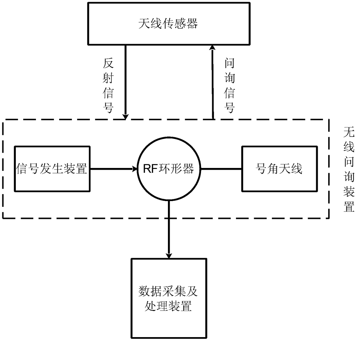
[0025] Such as figure 1 As shown, the embodiment of the present invention is based on a microstrip antenna sensor fatigue crack growth monitoring system, including a microstrip antenna sensor, a wireless interrogation device, and a data acquisition and processing device;

[0026] The microstrip antenna sensor is pasted on the tested object;

[0027] The wireless interrogation device includes a signal generating device, an RF circulator and a horn antenna, the signal generating device is connected to the horn antenna through the RF circulator, and the signal generating device generates a wireless i...


PUM

PropertyMeasurementUnit
Resonant frequencyaaaaaaaaaa

Abstract

The invention discloses a fatigue-crack propagation monitoring system based on a microstrip antenna sensor and a monitoring method thereof, wherein the fatigue-crack propagation monitoring system comprises a microstrip antenna sensor, a wireless inquiry device and a data acquisition and processing device; the microstrip antenna sensor is stuck on a tested testpiece; the wireless inquiry device comprises a signal generation device, an RF (Radio-Frequency) circulator and a horn antenna; the signal generation device is connected with the horn antenna by the RF circulator; the wireless inquiry device sends inquiry signals to a wireless sensor by the horn antenna and receives reflected signals of the antenna sensor; the data acquisition and processing device is connected with the RF circulatorand is used for receiving and processing the signals from the wireless inquiry device and generating the change of the resonance frequency of the antenna sensor and the length and the direction of thecrack propagation in the process of fatigue-crack propagation. The fatigue-crack propagation monitoring system and the monitoring method disclosed by the invention have the advantages that the wireless and online real-time monitoring for the length and the direction of the fatigue-crack propagation can be realized.

Description

technical field [0001] The invention relates to the field of metal structure health monitoring, in particular to a fatigue crack growth monitoring system based on a microstrip antenna sensor and a monitoring method thereof. Background technique [0002] Metal structures are widely used in modern mechanical equipment, civil engineering, marine structures, aerospace and other fields. In the long-term loading process, various damages will inevitably occur to the metal structure. Fatigue cracks are the most common form of failure in metal structures, and their characteristics are: in the initial stage of crack formation, the metal structure can still work normally, but when the cracks expand to a certain extent under alternating loads, catastrophic consequences may occur. In order to ensure the safe operation of metal structures and extend their service life as much as possible, it is common practice to use sensors to monitor their health. [0003] After decades of research on...

Claims


Application Information

Patent Timeline
Patent Type & Authority Applications(China)
IPC IPC(8): G01N3/06G01N3/32
CPCG01N3/066G01N3/32G01N2203/0005G01N2203/0073G01N2203/0617
Inventor 刘志平毛艳飞陈凯周凯孔璞萍
Owner WUHAN UNIV OF TECH
Why Eureka
Try Eureka