Metal crack detector based on macroscopic graphene conformal microstrip antenna and detection method

A technology of a microstrip antenna and a detection method, which is applied in directions such as antenna support/installation device, frequency measurement device, radiation element structure, etc., can solve the problems of poor detection accuracy, high price and short detection distance, etc. The effect of monitoring, convenient production and reasonable structure

Pending Publication Date: 2021-04-30
武汉汉烯科技有限公司
View PDF7 Cites 2 Cited by
  • Summary
  • Abstract
  • Description
  • Claims
  • Application Information

AI Technical Summary

Problems solved by technology

However, the above methods have obvious disadvantages. For example, eddy current detection technology has shortcomings such as small detection range, short detection distance, poor detection accuracy, and can only detect cracks close to the surface. Ultrasonic detection technology has complex signal processing process, high price and cost. Shortcomings such as detection of blind spots, high cost of infrared imaging detection, and complicated detection process
[0004] In recent years, the metal crack detection technology based on the microstrip antenna sensor has received a lot of research due to its advantages of simple fabrication, real-time detection, high sensitivity, and low price, but the current research mainly uses metal as the radiator of the microstrip antenna Due to the poor flexibility of the metal itself, the current microstrip antenna sensor mainly detects cracks in the planar metal structure. At the same time, due to the poor corrosion resistance and easy oxidation of the metal, it is difficult to work stably for a long time in harsh environments. These problems are extremely serious. The limitations of metal crack detection using pico-strip antenna sensors

Method used


Image

  • Metal crack detector based on macroscopic graphene conformal microstrip antenna and detection method
  • Metal crack detector based on macroscopic graphene conformal microstrip antenna and detection method
  • Metal crack detector based on macroscopic graphene conformal microstrip antenna and detection method

Examples


Embodiment approach

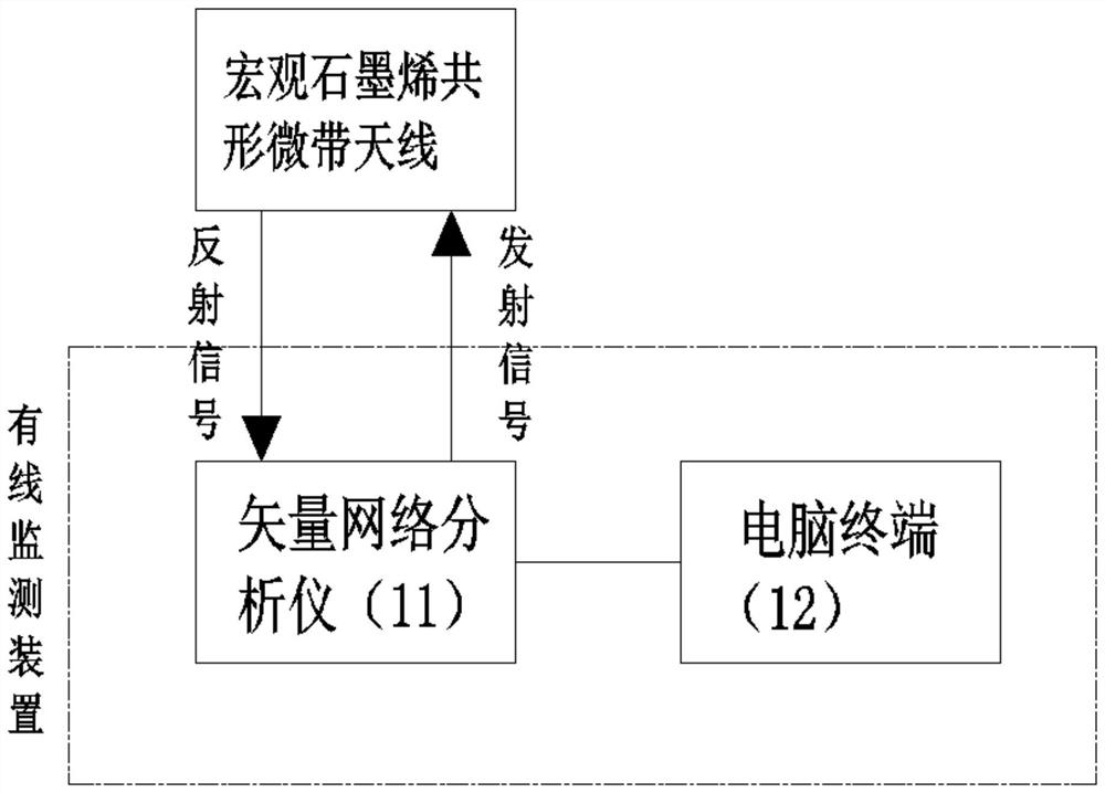
[0040] As an implementation, the wired detection device includes a vector network analyzer 11 and a computer terminal 12, the vector network analyzer 11 is connected with the macroscopic graphene conformal microstrip antenna, and the vector network analyzer 11 is used to The macroscopic graphene conformal microstrip antenna feeds, and receives the resonant frequency transmitted by the macroscopic graphene conformal microstrip antenna, and transmits the resonant frequency data to the computer terminal 12, and the computer terminal 12 is used to process the resonant frequency data Get the length and direction of the crack, and reflect the length and direction of the crack on the metal structure to be tested according to different frequency shifts;

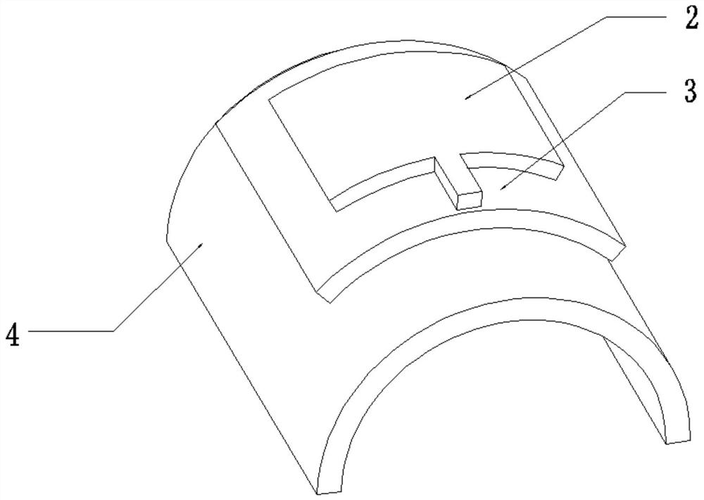
[0041]As an implementation, the macroscopic graphene conformal microstrip antenna is provided with an SMA joint, and the vector network analyzer 11 is connected to the SMA joint by a coaxial line to realize real-time detection of the ...


PUM

PropertyMeasurementUnit
thicknessaaaaaaaaaa
electrical conductivityaaaaaaaaaa

Abstract

The invention relates to a metal crack detector based on a macroscopic graphene conformal microstrip antenna. The metal crack detector comprises a macroscopic graphene film and a flexible dielectric substrate, wherein the macroscopic graphene film is arranged on the upper surface of the flexible dielectric substrate, the macroscopic graphene film and the flexible dielectric substrate form a macroscopic graphene conformal microstrip antenna, and the lower surface of the flexible dielectric substrate is adhered to the outer surface of a metal structure to be measured; and the macroscopic graphene conformal microstrip antenna is externally connected with a wired detection device, and the wired detection device is used for detecting the resonant frequency of the macroscopic graphene conformal microstrip antenna and obtaining the length and direction of the crack according to the frequency data. According to the invention, real-time detection on whether the complex curved surface metal structure has cracks can be realized, and detection on the length and direction of the cracks can be realized.

Description

technical field [0001] The invention relates to the technical field of graphene material application, in particular to a metal crack detector and detection method based on a macroscopic graphene conformal microstrip antenna. Background technique [0002] In today's society, metal structures are widely used in aerospace, marine ships, automobile manufacturing, mechanical equipment and civil engineering. Under long-term loads and harsh environments, it is difficult to avoid cracks in metal structures. When metal cracks begin to form , the metal structure can still work normally, but if the detection of cracks is not timely at this time, when the cracks continue to expand to a certain extent, it will cause extremely serious consequences. At present, metal cracks have become the primary factor affecting the normal work of metal structures. To ensure that the metal structure can work safely and for a long time, it is very necessary for the crack detection of the metal structure. ...

Claims


Application Information

Patent Timeline
Patent Type & Authority Applications(China)
IPC IPC(8): G01R23/02H01Q1/22H01Q1/38
CPCG01R23/02H01Q1/22H01Q1/38
Inventor 何大平童聪杨应平
Owner 武汉汉烯科技有限公司
Why Eureka
Try Eureka