Rotatable fixture for irregular objects
A rotating fixture and irregular technology, applied in the direction of manufacturing tools, metal processing equipment, auxiliary welding equipment, etc., can solve the problems of positioning at the axis of the fixture, inability to locate, troublesome positioning, etc., to ensure construction safety and protect the hydraulic system , The effect of easy disassembly and assembly
- Summary
- Abstract
- Description
- Claims
- Application Information
AI Technical Summary
Problems solved by technology
Method used
Image
Examples
Embodiment 1
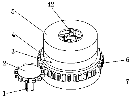
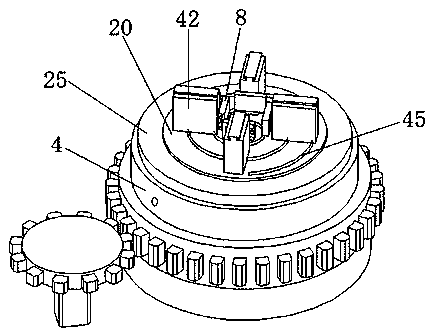
[0030] Embodiment 1: A rotatable fixture for irregular objects, constituted as Figure 1-6Shown includes the chuck body 4, the material of the chuck body 4 is low carbon steel, the upper part of the chuck body 4 is fixed with a ring bracket 5, the ring bracket 5 is provided with a first through hole 27, and the inner side of the ring bracket 5 is provided with a T-shaped Groove 26; Chuck body 4 below is provided with support assembly 7, and described support assembly 7 comprises circular ferrule 37, and circular ferrule 37 top is provided with second circular groove 44, and the center of second circular groove 44 is provided with The third through hole 46, the top of the circular ferrule 37 is fixed with the chuck body 4, the second circular groove 44 and the third through hole 46 form a hollow part, and the hollow part is pierced with the fixed shaft 30, and the circular ferrule 37 can be Rotates around a fixed axis 30 . The side of the chuck body 4 is provided with a rack 6...
Embodiment 2
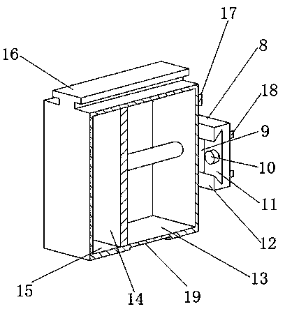
[0031] Example 2: As a specific implementation, the rotatable fixture for irregular objects such as figure 2 As shown, in order to adapt to the clamping work of irregular objects, the jaw 43 is pierced with an I-shaped rod 8, and the inside of the jaw 43 is provided with a jaw oil inlet chamber 15 and a jaw oil outlet chamber 13; the oil pan 25 is provided with a relief valve 38 inside, one end of the relief valve 38 is connected with the oil pan oil inlet chamber 22, and the other end is connected with the P port of the second reversing valve 39; the jaw oil inlet chamber 15 is connected with a third pressure gauge 40. The thrust of the I-shaped rod can be calculated according to the third pressure gauge. The claw oil inlet chamber 15 is connected to the A port of the second reversing valve 39, and the claw oil outlet chamber 13 is connected to the B port of the second reversing valve 39. , the R port of the second reversing valve 39 is connected to the fuel tank 29, the S p...
PUM
 Abstract
Description
Claims
Application Information
 - R&D
- Intellectual Property
- Life Sciences
- Materials
- Tech Scout
- Unparalleled Data Quality
- Higher Quality Content
- 60% Fewer Hallucinations
Browse by: Latest US Patents, China's latest patents, Technical Efficacy Thesaurus, Application Domain, Technology Topic, Popular Technical Reports.
© 2025 PatSnap. All rights reserved.Legal|Privacy policy|Modern Slavery Act Transparency Statement|Sitemap|About US| Contact US: help@patsnap.com


