
Tubing processing and branching conveying mechanism

A transmission mechanism and branching technology, applied in the direction of metal processing, etc., can solve the problems of low degree of automation, difficult to meet the processing requirements, and low efficiency of pipe punching processing, so as to achieve reasonable structure design, improve automation degree and processing efficiency Effect

Inactive Publication Date: 2018-09-21
TONGXIANG TANGCHAO ADVERTISEMENT CO LTD
View PDF0 Cites 14 Cited by
  • Summary
  • Abstract
  • Description
  • Claims
  • Application Information

AI Technical Summary

Problems solved by technology

During the production and processing of pipes, for metal pipes, it is necessary to uniformly cut the longer pipes into shorter pipes one by one, and the cut pipes are connected to the sides at both ends. The airtight structure, in order to better install and use the pipe material in the subsequent process, it is necessary to punch holes on the side of the pipe material. For punching the side of the material, workers need to manually place the tubes one by one on the clamping mechanism, and then use the punching mechanism to manually punch the side of the tube. There are many tube processing procedures, and workers need high Frequent clamping and picking of the pipe material, the labor intensity of the workers is relatively high, the efficiency of the pipe material punching process is low, and the automation degree of the entire pipe material feeding and punching process is low. The existing pipe material punching mechanism It is also difficult to realize the automatic and continuous feeding of the pipe material, and it is also difficult to move the pipe material to the required punching processing station smoothly and accurately during the drilling process, resulting in that the quality of the pipe material punching cannot be guaranteed. After the perforated tube material is processed from the punching equipment, it is difficult to automatically transfer the processed tube material in separate routes. It is necessary for the worker to manually pick up the tube material and place it on the required conveying mechanism. The processing efficiency of pipe material transmission is low, and it is difficult to meet the needs of processing and use

Method used


Image

  • Tubing processing and branching conveying mechanism
  • Tubing processing and branching conveying mechanism
  • Tubing processing and branching conveying mechanism

Examples


Embodiment Construction

[0017] In order to further describe the present invention, a specific implementation of a pipe material processing branch transmission mechanism will be further described below in conjunction with the accompanying drawings. The following examples are explanations of the present invention and the present invention is not limited to the following examples.

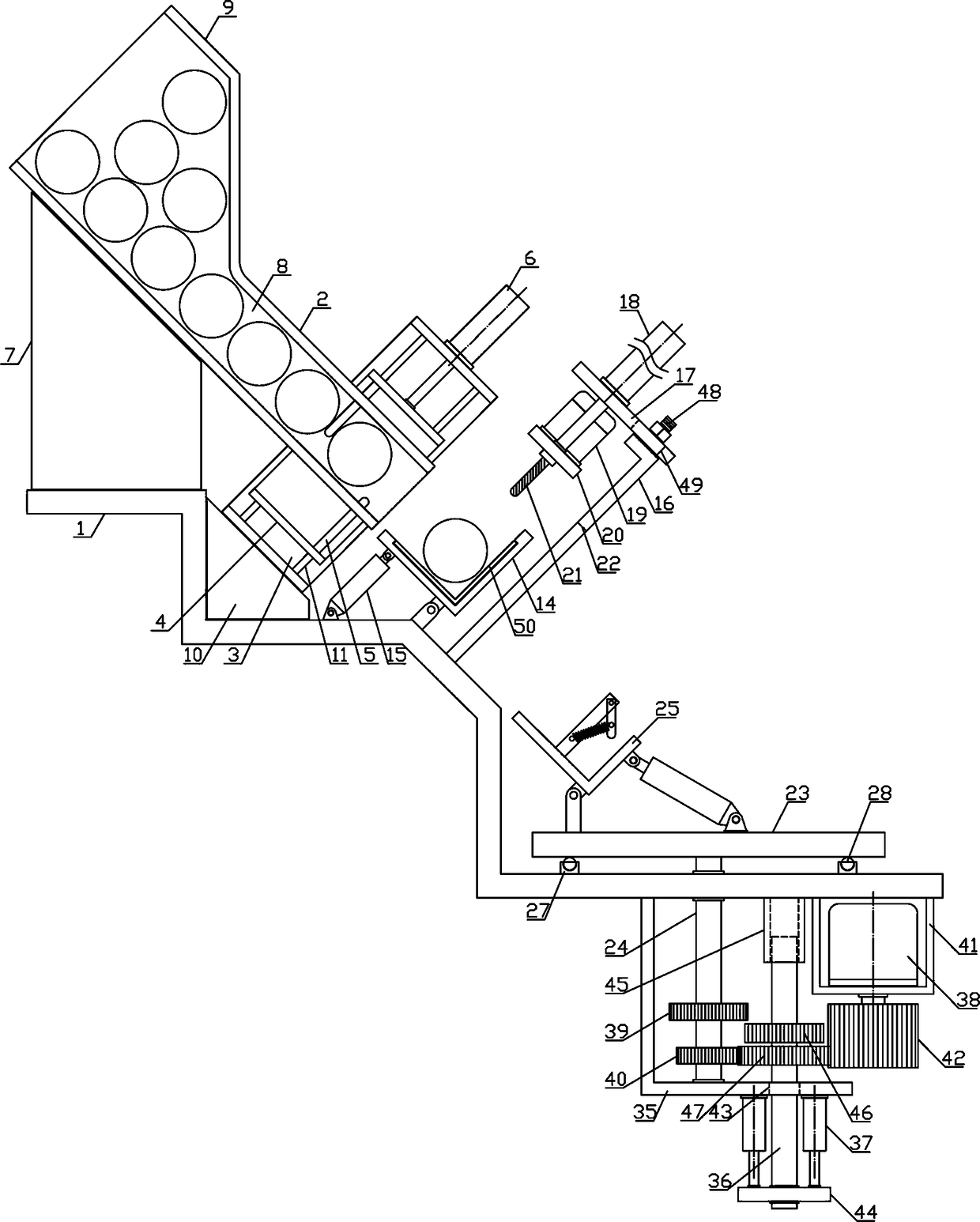
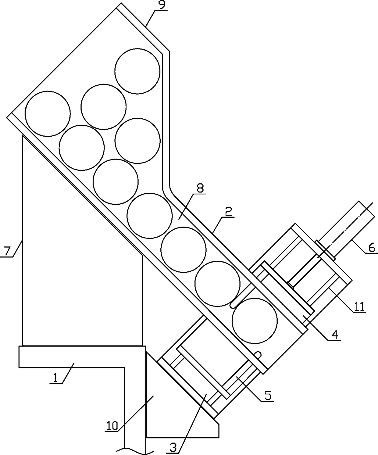
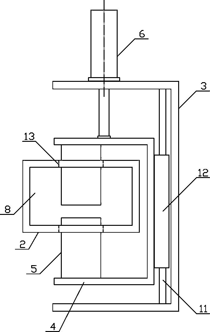
[0018] Such as figure 1 As shown, a pipe material processing branch transmission mechanism of the present invention includes a processing base 1, a feeding mechanism, a punching mechanism and a material guiding mechanism. The mechanism is horizontally and fixedly arranged on the upper side below the processing base 1, and the punching mechanism is obliquely and fixedly arranged on the processing base 1 between the blanking mechanism and the material guiding mechanism. Such as figure 2 , image 3 As shown, the blanking mechanism of the present invention includes a lower pipe material pipe 2, a lifting bracket 3, a retainin...


PUM


Abstract

The invention discloses a tubing processing and branching conveying mechanism, and belongs to the field of material processing and conveying mechanical equipment. A punching mechanism of the tubing processing and branching delivery mechanism is obliquely and fixedly arranged on a processing base between a blanking mechanism and a guiding mechanism, a tubing storage hopper is arranged on the upperside of a tubing blanking pipe in a communicated mode, a punching rotating rod is rotatably connected with the output end of a punching motor at the middle part of the upper side of a lifting connecting board, a board rotating air cylinder is obliquely arranged between a punching bearing board and the processing base, a tubing bearing mechanism is arranged on one side above a guiding disc in the radial direction of the guiding disc, branching conveyor belts are horizontally and symmetrically arranged on the parts, on the two sides of the guiding disc, of the processing base in the radial direction of the guiding disc, and a driving mechanism is arranged on the part, on one side of the lower end of a guiding rotating shaft, on the processing base. The tubing processing and branching delivery mechanism is reasonable in structural design, tubing can be subjected to steady and intermittent blanking one by one and subjected to punching processing, and the processed tubing can be subjected to branching conveying, so that the tubing processing and conveying automation degree is improved, and the requirements of processing use are met.

Description

technical field [0001] The invention belongs to the field of material processing and conveying mechanical equipment, and in particular relates to a pipe material processing branch conveying mechanism, which is mainly used in the field of pipe material continuous conveying and punching processing. Background technique [0002] Pipe is the material used to make pipe fittings. Different pipes use different pipes. The quality of pipes directly determines the quality of pipes. Pipes are necessary materials for construction projects. Commonly used are water supply pipes, drain pipes, gas pipes, and heating pipes. Pipes, wire conduits and rainwater pipes, etc., with the development of science and technology, the pipes used in home decoration have also experienced from ordinary cast iron pipes, cement pipes, reinforced concrete pipes and asbestos cement pipes to ductile iron pipes, galvanized steel pipes, plastic pipes and The development process of aluminum-plastic composite pipe. ...

Claims


Application Information

Patent Timeline
Patent Type & Authority Applications(China)
IPC IPC(8): B23Q7/00
CPCB23Q7/00
Inventor 裘国贤
Owner TONGXIANG TANGCHAO ADVERTISEMENT CO LTD
Learn More