Plastic film blanking device

A plastic film and punching technology, applied in the field of plastic film punching devices, can solve the problems of high cost, pipeline production hindering the progress of the project, and affecting the quality of punching materials.

Inactive Publication Date: 2018-09-21
郑 丽凤
View PDF0 Cites 4 Cited by
  • Summary
  • Abstract
  • Description
  • Claims
  • Application Information

AI Technical Summary

Problems solved by technology

[0003] In view of the deficiencies in the prior art, the purpose of the present invention is to provide a plastic film punching device to solve the problem that the plastic film punching device has a lack of operations on residue removal and burr polishing after punching, which may easily cause residues t

Method used


Image

  • Plastic film blanking device
  • Plastic film blanking device
  • Plastic film blanking device

Examples


Embodiment Construction

[0024] In order to make the technical means, creative features, goals and effects achieved by the present invention easy to understand, the present invention will be further described below in conjunction with specific embodiments.

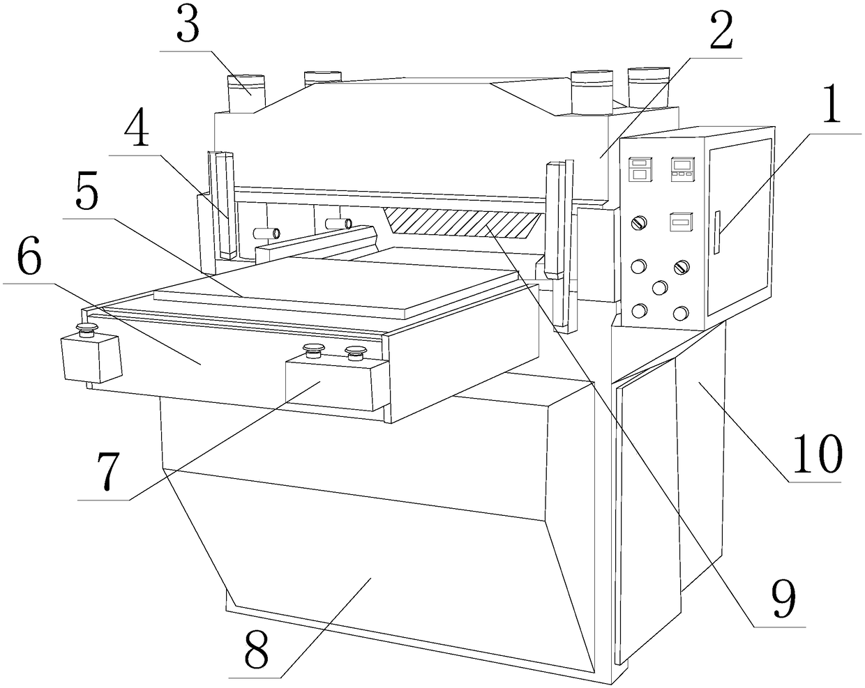
[0025] see Figure 1-Figure 5, the present invention provides a plastic film punching device: its structure includes: integrated electric control box 1, punching tool holder block 2, gas-liquid pressurized cylinder 3, support column tube 4, film processing table 5, slide rail transmission Groove 6, emergency stop button seat 7, anti-collision shell cover 8, trapezoidal blade 9, motor box base 10, described gas-liquid booster cylinder 3 is nested with the conduit of slide rail transmission groove 6 and is integrated, and described gas-liquid The pressurized cylinder 3 is provided with more than two and runs through the four corners of the blanking knife rest block 2 longitudinally, and the punching knife rest block 2 is welded into one body with th...


PUM


Abstract

The invention discloses a plastic film blanking device. The plastic film blanking device comprises a centralized electric control box, a blanking cutter frame block, an air-liquid pressure cylinder, asupport column pipe, a film machining table, a slide rail transmission groove, a sudden stop button base, an anti-collision shell cover, a trapezoidal blade and a motor box base; the air-liquid pressure cylinder and a guide pipe of the slide rail transmission groove are engaged as a whole; the air-liquid pressure cylinder is provided with a gear transmission mechanism, a gas transmission device,a tooth block switching device, a ratchet rotating mechanism, a shaft rod ejecting device, a hydraulic cylinder compression mechanism, a pneumatic cylinder pushing mechanism and a double-outlet-rod pressure device; the hydraulic and pneumatic cooperation effect of the plastic film blanking device is high; hydraulic outlet water scours and blanks residues, so that the next material blanking qualityis not influenced; and burrs are flatly blown by applying the air pressure to finish the flatness of film surfaces beforehand, so that the quick implementation of later production line is accelerated, the overall working efficiency is improved, and the short-time high-quality operation is achieved.

Description

technical field [0001] The invention relates to a plastic film blanking device, which belongs to the field of film blanking devices. Background technique [0002] When forming a through hole in a plastic film, the plastic film is usually punched out by a cylindrical punching knife. The punching knife moves toward the plastic film and the die, and presses against the plastic film. The plastic film is sandwiched between the punching knife and the die. Therefore, the plastic film is punched by the punching knife and the die to form a through hole on the plastic film, and the punching knife is moved toward the plastic film and the carrying table, and pressed to the plastic film, and the plastic film is clamped between the punching knife and the carrying table. Between the bearing tables, and the punching knife is rotated by the rotary drive mechanism, thereby punching the plastic film. The plastic film punching device commonly used in the current technology is short of residue r...

Claims


Application Information

Patent Timeline
IPC IPC(8): B26F1/40B26D5/12B26D7/18B26D7/22B26D7/00
CPCB26F1/40B26D5/12B26D7/00B26D7/1845B26D7/22
Inventor 郑丽凤
Owner 郑 丽凤
Why Eureka
Try Eureka