Conveying and overturning mechanism for square tanks

A technology for overturning mechanisms and tanks, which is applied in the direction of conveyors, conveyor objects, transportation and packaging, etc. It can solve problems such as flattening and twisting of square tanks, easy failure of multi-drive mechanisms, and inability of square tanks to achieve structural well-designed effects

Inactive Publication Date: 2018-09-21
屠明州
View PDF0 Cites 5 Cited by
  • Summary
  • Abstract
  • Description
  • Claims
  • Application Information

AI Technical Summary

Problems solved by technology

During the production and processing of the existing square tanks, for small-scale tank-making enterprises, the production and processing of the formed square tanks is generally manually turned over to enable the upper cover to be processed, and the work intensity of the workers is relatively high and the working hours Long, it is difficult to meet the needs of large-scale can production. In the existing large-scale can production enterprises, in the process of vertically turning the square cans produced and processed in the previous process, the manipulator is generally used to automatically turn over, but the manipulator is used to turn over , first of all, it is necessary to grab the square tank body. In the process of grabbing the square tank body, the existing manipulator often causes the square tank body to fall off due to poor grasping in the proc

Method used


Image

  • Conveying and overturning mechanism for square tanks
  • Conveying and overturning mechanism for square tanks
  • Conveying and overturning mechanism for square tanks

Examples


Embodiment Construction

[0013] In order to further describe the present invention, the specific implementation of a square tank conveying and turning mechanism will be further described below in conjunction with the accompanying drawings. The following examples are explanations of the present invention and the present invention is not limited to the following examples.

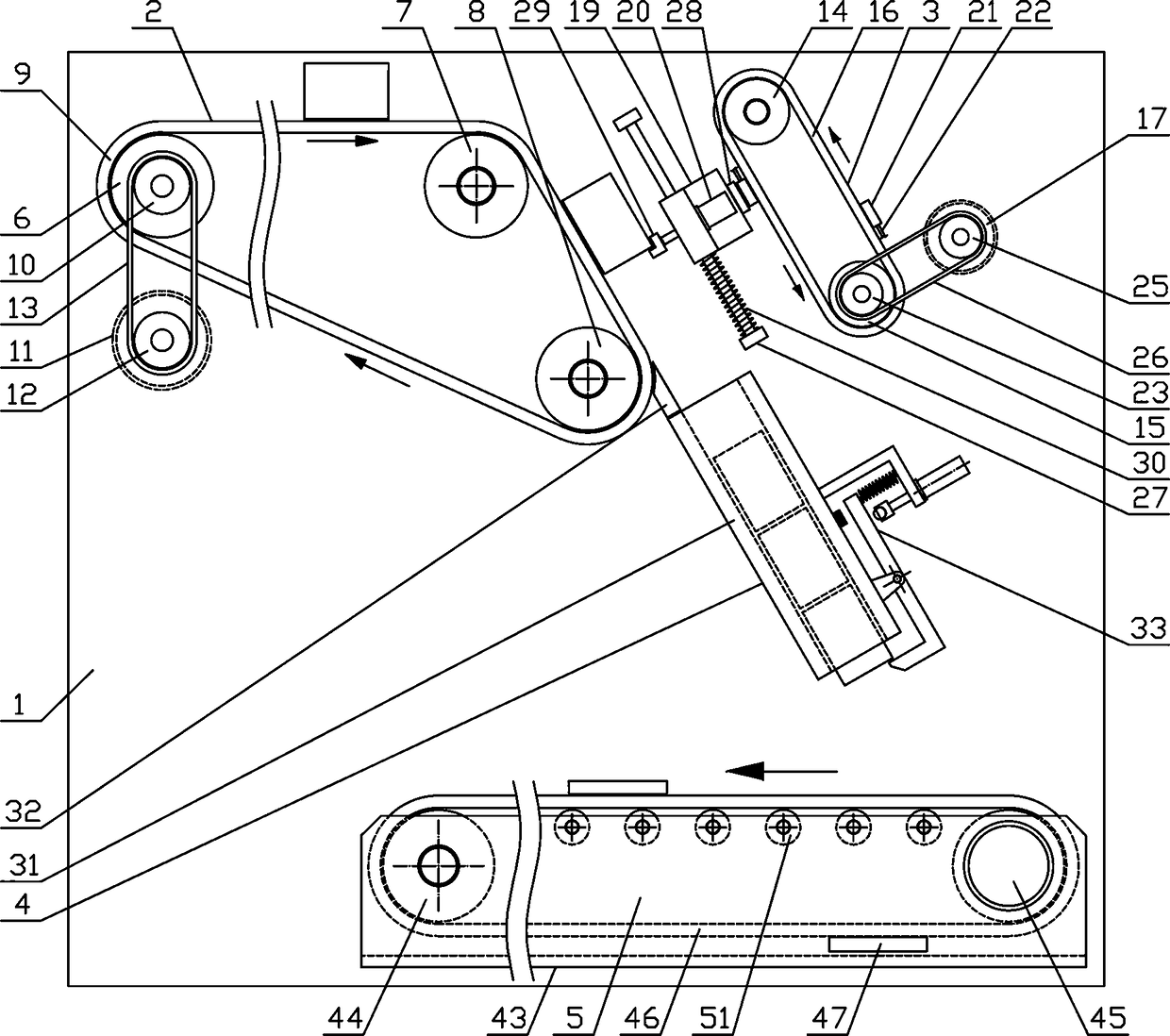
[0014] Such as figure 1 As shown, a square can transfer mechanism of the present invention includes a fixed bracket 1, a front tank transfer mechanism 2, a tank holding mechanism 3, a tank guide mechanism 4 and a rear tank transfer mechanism 5, and the front tank transfer mechanism 2 is horizontally arranged on the fixed bracket 1 On the upper side, the tank holding mechanism 3 is arranged obliquely downward on the fixed bracket 1 on the side of the front tank transfer mechanism 2, the tank guide mechanism 4 is arranged obliquely downward on the fixed bracket 1 on the lower side of the front tank transfer mechanism 2, and the rear tan...


PUM


Abstract

The invention discloses a conveying and overturning mechanism for square tanks, and belongs to the field of mechanical equipment for continuous conveying of tanks. A tank carrying mechanism is arranged on a fixing support at one side of a front tank conveying mechanism obliquely and downwardly. A tank guide mechanism is arranged on a fixing support at the lower side of the front tank conveying mechanism obliquely and downwardly. A rear tank conveying mechanism is horizontally and fixedly arranged on a fixing support at the lower side of the tank guide mechanism. A tank carrying support is arranged on a lifting guide rod slidably. A tank-carrying clamp plate is arranged at the output end of a tank-carrying air cylinder fixedly. A reset spring sleeves the lifting guide rod on the lower sideof the tank carrying support. A tank guide pipeline is arranged on a fixing support at the lower side of a front tank conveying belt obliquely and downwardly. A tank clamping mechanism is arranged onthe upper side of the lower end of the tank guide pipeline. A plurality of material conveying electromagnets are arranged on the outer side of a rear tank conveying belt evenly. The conveying and overturning mechanism has the advantages that the structural design is reasonable, the square tanks can be conveyed efficiently and continuously and can be also overturned smoothly and vertically one by one, and production and application requirements are met.

Description

technical field [0001] The invention belongs to the field of mechanical equipment for continuous conveying of cans, and in particular relates to a conveying and turning mechanism for square cans, which is mainly used in the continuous turning process of square cans. Background technique [0002] Tanks mainly refer to cylindrical airtight containers that can be used to store materials. Tanks play an increasingly important role in our production and life due to their high efficiency in storing items and the convenience of carrying them. Tanks are classified according to their appearance and shape. , can be divided into square cans and round cans. There are many materials for producing cans, mainly including plastic cans and metal cans. Compared with plastic cans, metal cans are more widely used in our industrial production and daily life. The advantages of metal cans Obviously, its airtight performance is very good, it can resist high internal pressure, it can ensure that the ...

Claims


Application Information

Patent Timeline
IPC IPC(8): B65G47/252
CPCB65G47/252B65G2201/0252
Inventor 屠明州
Owner 屠明州
Why Eureka
Try Eureka