Method for cooling inner wall of waste heat boiler during adjustment of blowpipe of fuel-steam unit

A waste heat boiler and steam unit technology, which is applied in the steam generation method, the steam generation method using heat carrier, the steam generation and other directions, can solve the problem of lack of safe operation, shorten the construction period, improve the commissioning efficiency, and avoid the waste heat boiler equipment. damage effect

Active Publication Date: 2018-09-21
ELECTRIC POWER SCI & RES INST OF STATE GRID TIANJIN ELECTRIC POWER CO +2
View PDF5 Cites 0 Cited by
  • Summary
  • Abstract
  • Description
  • Claims
  • Application Information

AI Technical Summary

Problems solved by technology

[0003] When the operating personnel operate the steam drums of the waste heat boiler under pressure to discharge water during the shutdown cooling period, the temperature of the inner tube wall of the waste heat boiler will continue to be maintained at a relatively high temperature (80°C-100°C) due to various improper operations. The temperature difference between the inner tube wall of the waste heat boiler and the water is greater than 55°C. In such a situation, the temperature of the inner tube wall of the waste heat boiler can only be reduced to the appropriate temperature of the upper water by natural cooling at present, and it has not been able to achieve a rapid and effective reduction. The method of high temperature in the inner tube wall of the waste heat boiler caused by improper operation leads to the lack of necessary technical support for the safe operation of the gas-steam combined cycle unit during the commissioning blowpipe

Method used


Image

  • Method for cooling inner wall of waste heat boiler during adjustment of blowpipe of fuel-steam unit
  • Method for cooling inner wall of waste heat boiler during adjustment of blowpipe of fuel-steam unit

Examples


Embodiment Construction

[0024] The embodiments of the present invention will be described in further detail below in conjunction with the accompanying drawings. It should be emphasized that the following embodiments are illustrative, not restrictive, and should not be used as limitations of the present invention.

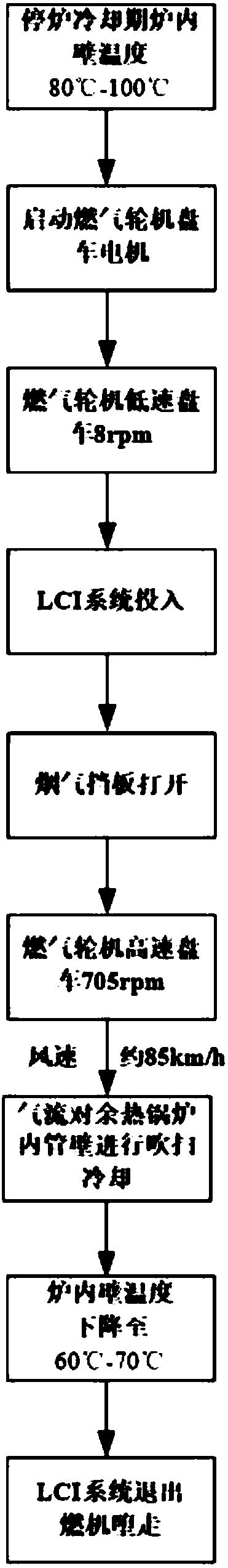
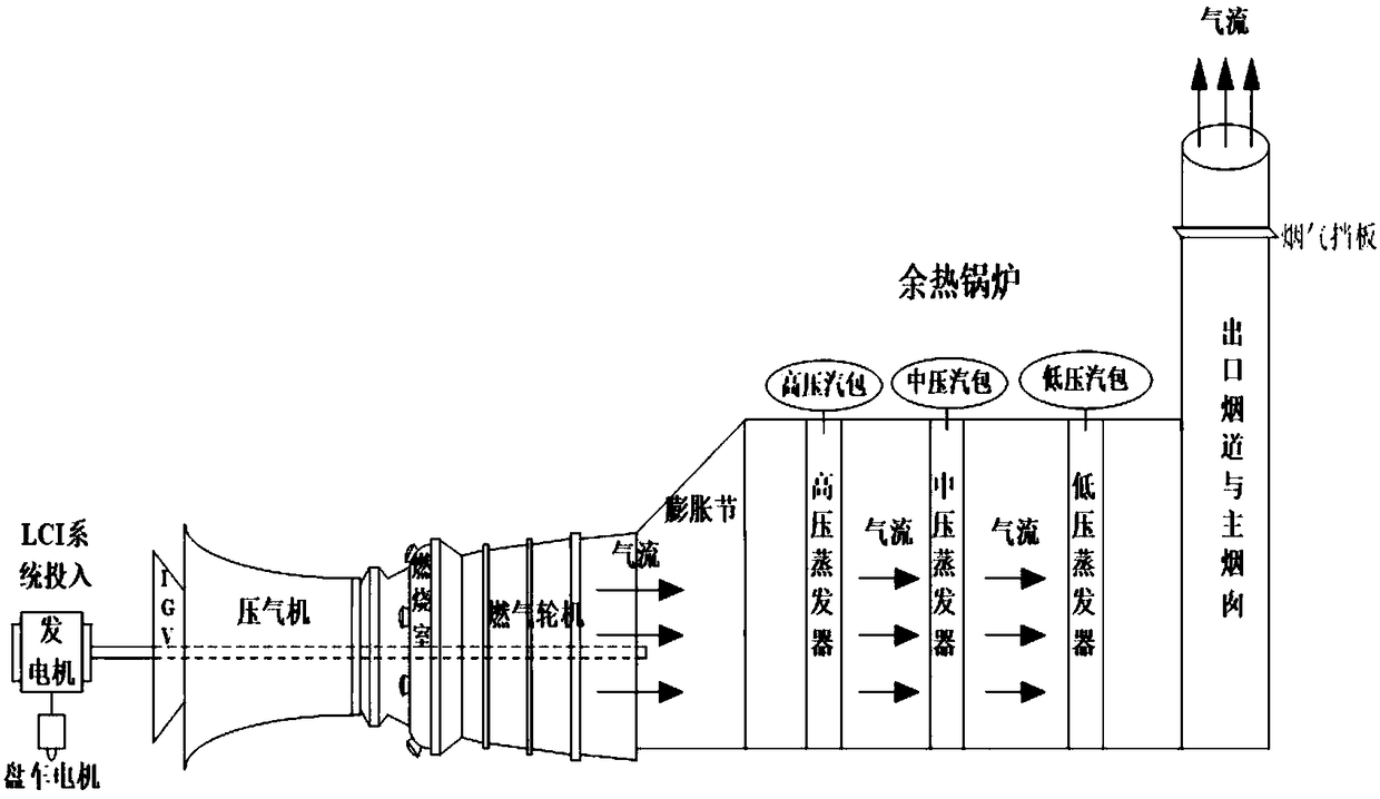
[0025] A cooling method for the inner wall of the waste heat boiler during the debugging and blowing of the gas-steam unit, such as figure 2 As shown, the equipment system used in this method includes: gas turbine, gas turbine cranking system, waste heat boiler, temperature measurement point on the inner wall of waste heat boiler, and the server of the operating unit control system, wherein the gas turbine cranking system includes gas turbine cranking motor and LCI system (Load Commutated Inverter, a speed-adjustable AC drive system specially designed to start gas turbines), such as figure 1 As shown, the method includes the following steps:

[0026] (1) Start the gas turbine cranking mo...


PUM


Abstract

The invention relates to a method for cooling the inner wall of a waste heat boiler during adjustment of a blowpipe of a fuel-steam unit. The method comprises the steps that (1) a gas turbine turningmotor is started, and a gas turbine is made to turn at a low speed, specifically, the rotation speed is 8 rpm, and duration is 30 min; (2) an LCI system is started, the turning motor disengages and exits, and the gas turbine is turned at a high speed; (3) a smoke baffle at an outlet flue of the waste heat boiler is opened; and (4) wind power generated by an impeller of a gas turbine is blown towards the inner pipe wall of the waste heat boiler for cooling, the LCI system exits when the temperature of the inner wall of the waste heat boiler is decreased to be about 60-70 DEG C, the idling rotation speed of the gas turbine is gradually decreased to 0 rpm, and the smoke baffle is closed. With adoption of the method, the gas turbine turning at a high speed is used as an electric fan, the generated strong airflow is blown towards the inner pipe wall of the waste heat boiler for cooling, and the phenomenon of high temperature of the inner pipe wall of the waste heat boiler caused by variousreasons can be quickly and effectively solved.

Description

technical field [0001] The invention belongs to the technical field of safety of thermal power generation, and in particular relates to a method for cooling the inner wall of a waste heat boiler during debugging and blowing of a gas-steam unit. Background technique [0002] During the commissioning of the capital construction before the gas-steam combined cycle unit is put into production, in order to remove all kinds of sundries left in the superheater, reheater and steam pipeline during the manufacturing, transportation and installation of equipment and pipelines, the commissioning personnel must check the waste heat boiler Superheater, reheater, and steam pipes are blown, that is, steam flushing equipment and pipes. According to the "Guidelines for Steam Blowing of Thermal Power Construction Engineering Units", each waste heat boiler should be shut down for cooling at least twice during the blowing process. Each steam drum of the waste heat boiler should discharge water u...

Claims


Application Information

Patent Timeline
Patent Type & Authority Applications(China)
IPC IPC(8): F22B1/18F28G13/00F28G15/00
CPCF22B1/1892F28G13/00F28G15/00
Inventor 王梓越刘新利周连升张宇甘智勇王坤王建何少聪
Owner ELECTRIC POWER SCI & RES INST OF STATE GRID TIANJIN ELECTRIC POWER CO
Why Eureka
Try Eureka