Waste liquid discharging device, blood coagulation analyzer with waste liquid discharging device and discharge method

A waste liquid discharge and waste liquid technology, which is applied to chemical instruments and methods, cleaning methods and appliances, liquid variable capacity machinery, etc., can solve the problems of increasing the cost of the whole machine, restricting the use conditions, and quick and easy splashing, etc., to achieve extended Effect of service life, reduction of replacement times, and extension of service life

Inactive Publication Date: 2018-09-21
DIRUI MEDICAL TECH CO LTD
View PDF5 Cites 6 Cited by
  • Summary
  • Abstract
  • Description
  • Claims
  • Application Information

AI Technical Summary

Problems solved by technology

However, in order to ensure that the waste liquid in the cleaning tank will not overflow from the top of the cleaning tank during the cleaning process of the sampling needle, the waste liquid pump is required to be turned on all the time during the cleaning process, which shortens the service life of the waste liquid pump and may cause waste The liquid pump reaches the predetermined service life in a short period of time and needs to be replaced due to damage, which increases the maintenance cost of the whole machine
[0004] 2. Generally, it is necessary to use a negative pressure system alone to generate negative pressure on the closed waste liquid container. The waste liquid generated by cleaning is sucked into the waste liquid container by negative pressure, and finally the waste liquid pump passes through the pipeline from the bottom wall of the waste liquid container. The outlet directly pumps out the waste liquid, but in this set of negative pressure waste

Method used


Image

  • Waste liquid discharging device, blood coagulation analyzer with waste liquid discharging device and discharge method

Examples


Embodiment Construction

[0040] The present invention will be described in further detail below in conjunction with the accompanying drawings and embodiments.

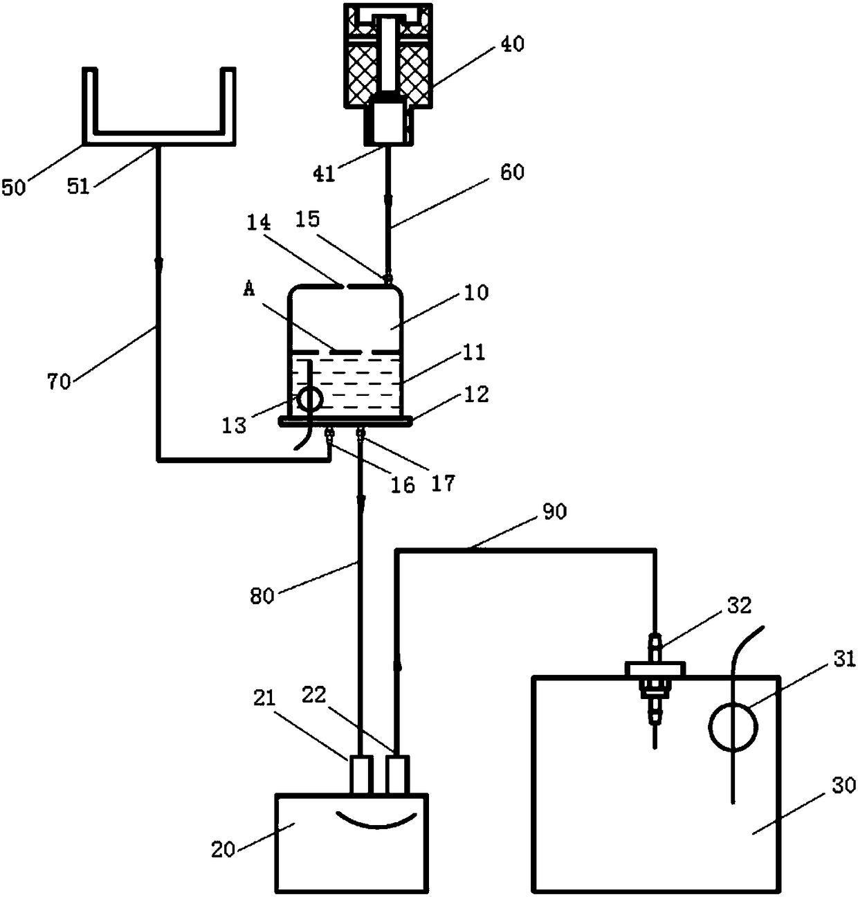
[0041] Such as figure 1 The waste liquid discharge device of the coagulation analyzer shown includes a transfer tank assembly 10, a waste liquid pump 20, a waste liquid barrel assembly 30 and a controller (not shown in the figure). The transfer tank assembly 10 is used for temporarily storing waste liquid, and it includes a first liquid level sensor 13, and the first liquid level sensor is arranged in the transfer tank assembly 10 for detecting the liquid level in the transfer tank assembly 10; the waste liquid The pump 20 includes an inlet 21 and an outlet 22, the inlet 21 communicates with the lower end surface of the transfer tank assembly 10; the waste liquid bucket assembly 30 communicates with the outlet 22 for storing waste liquid; and a controller, which is connected to the The waste liquid pump 20 is used to control the opening and c...


PUM


Abstract

The invention discloses a waste liquid discharging device, a blood coagulation analyzer with waste liquid discharging device and a discharging method. The waste liquid discharging device comprises: atransfer tank assembly, used for storing waste liquid, a first liquid level sensor which is arranged in the transfer tank assembly and is used for detecting the liquid level in the transfer tank assembly; a waste liquid pump, which comprises an inlet and an outlet, wherein the inlet is communicated with the lower end surface of the transfer tank assembly; a waste liquid barrel which is communicated with the outlet and is used for storing waste liquid; and a controller which is connected with the waste liquid pump and is used for controlling the start and stop of the waste liquid pump; the controller is also connected with the first liquid level sensor; when the first liquid level sensor detects that the liquid level in the transfer tank assembly reaches a preset liquid level, the first liquid level sensor issues an on signal to the controller, and the controller receives the signal and controls the waste liquid pump to start. The waste liquid discharging device, the blood coagulation analyzer with the waste liquid discharging device and the waste liquid discharging method realize the semi-automatic liquid discharge of the analyzer and prolong the service life of the waste liquid pump.

Description

technical field [0001] The invention relates to the technical field of medical equipment, in particular to a waste liquid discharge device, a coagulation analyzer with a waste liquid discharge device and a waste liquid discharge method. Background technique [0002] In the coagulation analysis instrument, a certain amount of waste liquid will be generated when cleaning the sampling needle and other executive parts. In order to effectively collect the generated waste liquid, the following schemes are currently adopted: [0003] 1. Generally, the waste liquid outlet at the lower end of the cleaning tank is directly connected to the waste liquid pump inlet with a pipeline, and the waste liquid pump outlet is connected to the waste liquid bucket outside the machine, and the waste liquid pump is directly used to collect the waste liquid generated by these cleaning needles. However, in order to ensure that the waste liquid in the cleaning tank will not overflow from the top of th...

Claims


Application Information

Patent Timeline
IPC IPC(8): G01N33/48F04B49/06B08B13/00
CPCG01N33/48B08B13/00F04B49/06
Inventor 张海强杨登志张建赵滨
Owner DIRUI MEDICAL TECH CO LTD
Why Eureka
Try Eureka