Concentrator

A technology of concentrators and current transformers, applied in the field of concentrators, can solve the problems of not disclosing the connection method of each component and PCB board, not disclosing the connection error of functional terminals, affecting the service life of functional terminals, etc., to increase space utilization, Reasonable and compact structure design, high reliability

Active Publication Date: 2018-09-21
NINGBO SANXING MEDICAL & ELECTRIC CO LTD
View PDF12 Cites 0 Cited by
  • Summary
  • Abstract
  • Description
  • Claims
  • Application Information

AI Technical Summary

Problems solved by technology

[0004] The concentrator is provided with a terminal box and a PCB board, wherein the terminal box is provided with various components such as voltage terminals, functional terminals, and transformers. The current concentrator, such as the patent number CN201220210623.8 (authorized announcement number is CN202662155U) Chinese utility model patent "an operation panel of a power consumption information concentrator", the operation panel of the concentrator includes a housing, and the housing is provided with a liquid crystal screen, an indicator light, an optical communication port, an RS232 communication port, a USB Interface, SIM card box, control keyboard, GPRS module, carrier module, main terminal and auxiliary terminal, main terminal includes current terminal and voltage terminal, auxiliary terminal includes remote signaling terminal, RS485Ⅱ cascading terminal, RS485Ⅰ meter reading terminal and spare terminal, Although the above-mentioned concentrator is provided with various components and the arrangement of each component, it does not disclose a reasonable connection method between each component and the PCB board, so that the installation of each component is more convenient and quick, and the installation disorder is prevented.
[0005] At present, the installation of current transformers usually adopts: for example, the Chinese utility model patent "end button box assembly of three-phase electric energy meter" whose patent number is CN201721315865.2 (authorized announcement number is CN207318556U), the end button box assembly includes: Terminal box, relay and transformer assembly, 4 voltage connector assemblies and circuit board; the left and right sides of the terminal box are provided with hooks and 2 positioning columns, and the relay and transformer assembly includes relay assembly and 3 current transformers, and each current transformer is provided with 2 connection pins; each current transformer is electrically connected to the relay assembly, and the relay assembly, each current transformer, each voltage connector assembly and the circuit board are connected to the The terminal box is connected, and the hook, two positioning columns and each connecting pin are all connected to the circuit board. This patent discloses the installation of the current transformer, but the current transformer is arranged outside the terminal box, which takes up a lot of space, and The current transformer is fixedly connected to the terminal box through screws, which increases the contact resistance. At the same time, the screw connection is prone to loose screws, and the reliability is not high.
In addition, there is no disclosure that the functional terminals are prone to connection errors, which increases the difficulty of connection; in addition, there is no disclosure that the functional terminals are easy to come into contact with water, dust, etc., which will affect the service life of the functional terminals

Method used


Image

  • Concentrator
  • Concentrator
  • Concentrator

Examples


Embodiment Construction

[0041] The present invention will be further described in detail below in conjunction with the accompanying drawings and embodiments.

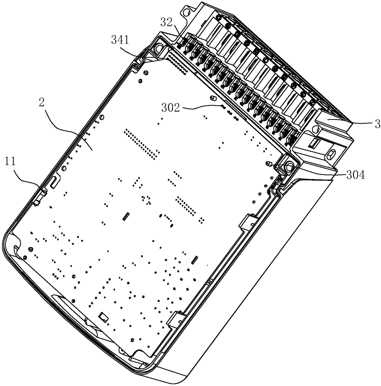
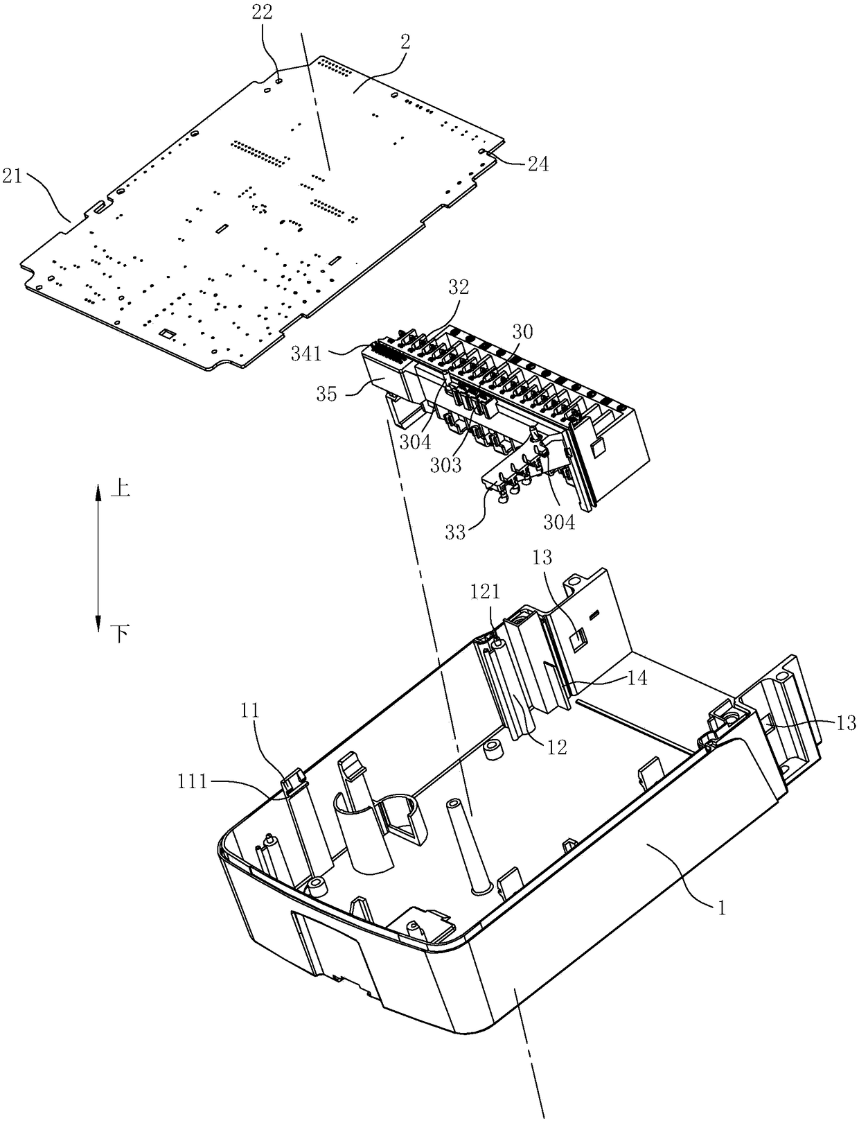
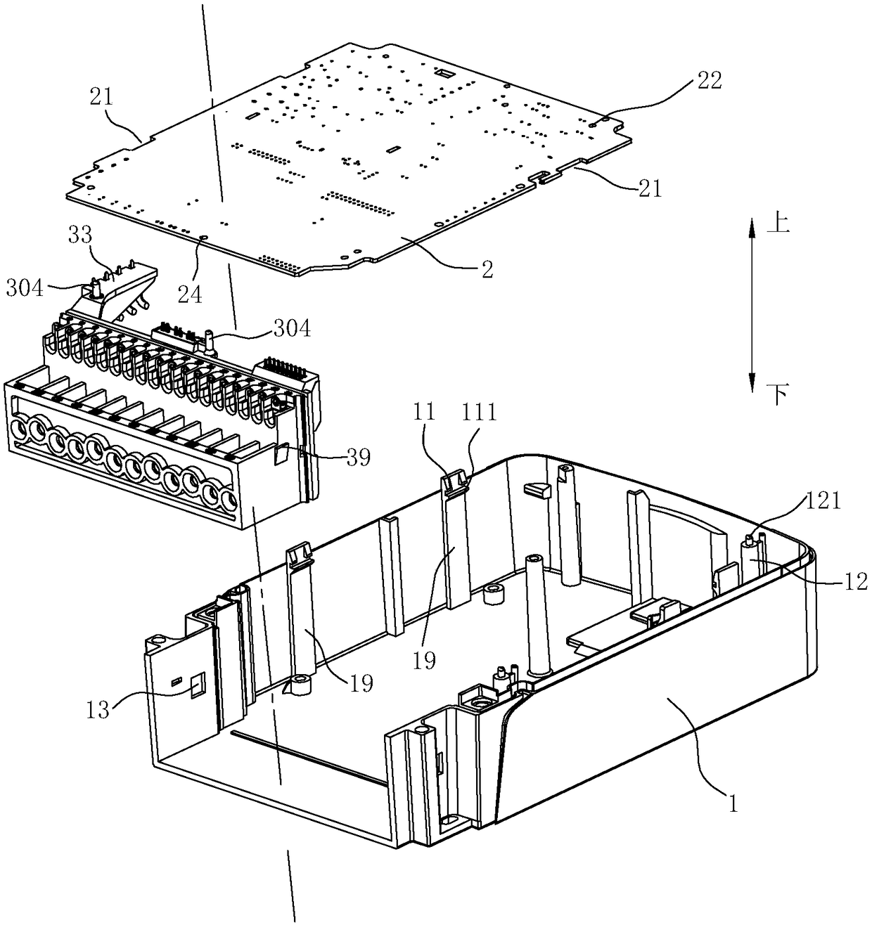
[0042] Such as Figure 1 to Figure 14 As shown, a concentrator according to an embodiment of the present invention includes a base 1, a terminal box 3 disposed on the base 1, and a current transformer 30, and the terminal box 3 is provided with functional terminals 32 and voltage terminals 32, wherein,

[0043] The upper side of the terminal button box 3 is provided with the first PCB board 2, and the terminal button box 3 is provided with the second PCB board 34 for concentrating the conductive columns 311 of the functional terminals 32, and the functional terminals 32 are connected to the first PCB board 34 through the second PCB board 34. The PCB board 2 is electrically connected. Specifically, the functional terminal 32 has a conductive post 321 extending downward, and the second PCB board 34 is provided with a through hole 342 for the con...


PUM


Abstract

The invention relates to a concentrator, which comprises a terminal box and a current transformer. A function terminal is arranged inside the terminal box, and a second PCB used for concentrating conductive pillars of the function terminal is also arranged inside the terminal box. The function terminal is electrically connected with a first PCB through the second PCB, and the second PCB is externally provided with a protection cover. The current transformer is inserted in the terminal button box and located on the upper side of the function terminal. The current transformer is equipped with asecond plug pin and is inserted in the second PCB through the second plug pin to be electrically connected with the second PCB. With the installation structure design of the function terminal, installation errors of the function terminal are prevented, and installation accuracy of the function terminal is enhanced; with the design of the protection cover, dust, water and the like are prevented from contacting with the second PCB and the function terminal so as to prolong service life; with the current transformer inserted in the terminal box, space usage of the current transformer is reduced,installation of the current transformer can be realized without the need of fixing with screws, and contact resistance when fixing with screws is lowered.

Description

technical field [0001] The present invention relates to a concentrator. Background technique [0002] The concentrator is the central management device and control device of the remote centralized meter reading system. It is responsible for regularly reading terminal data, system command transmission, data communication, network management, event recording, and data horizontal transmission. The concentrator is the connection terminal, A central connection point device for a computer or communication device. [0003] In a number of terminal-intensive areas, usually in order to reduce communication lines, the terminal is first connected to the concentrator, and then the concentrator is connected to the communication controller of the computer through a high-speed line. Therefore, the concentrator is also the best way to share lines and improve line utilization. An effective device. [0004] The concentrator is provided with a terminal box and a PCB board, wherein the termina...

Claims


Application Information

Patent Timeline
Patent Type & Authority Applications(China)
IPC IPC(8): G08C17/02H01F27/29H01F38/30H01R9/24
CPCH01R9/2425G08C17/02H01F27/29H01F38/30
Inventor 魏伟黄健陈欢林国庆
Owner NINGBO SANXING MEDICAL & ELECTRIC CO LTD
Why Eureka
Try Eureka