
Method and device with reactive power compensation fast switching function

A functional and fast technology, applied in the direction of reactive power compensation, reactive power adjustment/elimination/compensation, circuit devices, etc., can solve the problem that the time scale cannot meet the fast switching capacitors, etc., to achieve maintenance stability, economy, small size, etc. cost, the effect of reducing the amount of load shedding

Active Publication Date: 2018-09-21
SHENZHEN POWER SUPPLY BUREAU
View PDF2 Cites 5 Cited by
  • Summary
  • Abstract
  • Description
  • Claims
  • Application Information

AI Technical Summary

Problems solved by technology

Although the AVC and VQC currently used can also control the switching of capacitors, their action delay is generally about 30s, but they cannot meet the requirements of fast switching capacitors on the time scale.

Method used


Image

  • Method and device with reactive power compensation fast switching function
  • Method and device with reactive power compensation fast switching function
  • Method and device with reactive power compensation fast switching function

Examples


Embodiment Construction

[0052]In the following description, specific details such as specific system structures and technologies are presented for the purpose of illustration rather than limitation, so as to thoroughly understand the embodiments of the present invention. It will be apparent, however, to one skilled in the art that the invention may be practiced in other embodiments without these specific details. In other instances, detailed descriptions of well-known systems, devices, circuits, and methods are omitted so as not to obscure the description of the present invention with unnecessary detail.

[0053] In order to illustrate the technical solution of the present invention, the following will be described through specific embodiments in conjunction with the accompanying drawings.

[0054] The embodiment of the present invention provides a method with the function of fast switching of reactive power compensation, which is applied to the safety and stability control of the power system, and r...


PUM


Abstract

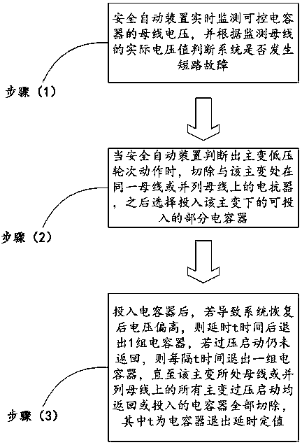
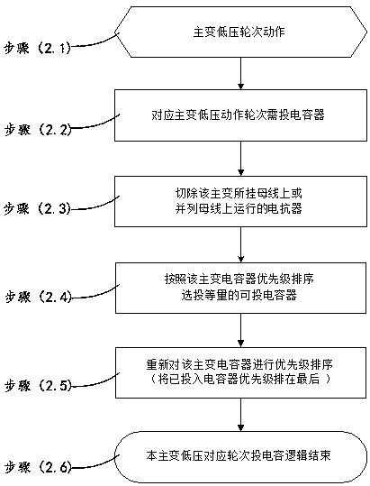
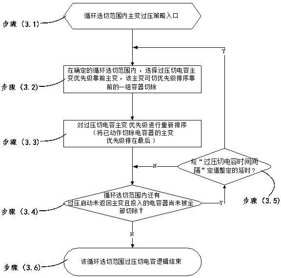
The invention discloses a method with a reactive power compensation fast switching function. The method mainly comprises a step of monitoring the bus voltage of a controllable capacitor in real time by using a safety automatic device and judging whether the system has a short circuit fault condition according to the monitoring of an actual voltage value of a busbar, a step of cutting off all the reactors on the same busbar or parallel busbar as a main transformer and then selecting to switch to a part of capacitors that can be switched under the main transformer, and a step of withdrawing a set of capacitors after a certain delay if over high voltage after system recovery is caused after switching to the capacitor, if overvoltage start still does not return, withdrawing a group of capacitors at regular intervals until all main transformer overvoltage on the same busbar or parallel busbar of the main transformer return or switched-on capacitors are removed. According to the method, thedynamic reactive power support capability of a receiving end power grid can be strengthened, the voltage stability of the power grid is improved, and a requirement of quickly switching on the capacitors under the condition of protection or switch rejection is achieved.

Description

technical field [0001] The invention relates to the technical field of power system safety and stability control, in particular to a method and a device with a reactive power compensation fast switching function. Background technique [0002] In the Southern Power Grid system, there are a large number of reactive power equipment installed in the stations of each voltage level, and the operation practice has found that even in the case of heavy load, some capacitors are in standby state. If the automatic device can be used to automatically put in the backup capacitor when the system voltage drops, the voltage stability of the system can be improved at a relatively small cost; in terms of control strategy, if the capacitor can be protected when the system fails or the switch refuses to move If it is not activated when the protection is correctly cut off, it can reduce the probability of capacitor action and prolong its life; in terms of input time, the smaller the action delay...

Claims


Application Information

Patent Timeline
Patent Type & Authority Applications(China)
IPC IPC(8): H02J3/18
CPCH02J3/1821Y02E40/30
Inventor 何晓峰程维杰程韧俐
Owner SHENZHEN POWER SUPPLY BUREAU
Learn More