Rotating target material capable of withstanding high-power sputtering, and preparation method of rotating target material

A rotating target, high-power technology, applied in the field of sputtering targets, can solve the problems of high-power sputtering, contamination of coating chambers and products, low bonding efficiency, etc., to reduce target surface nodules and target The material is broken down and the target material is cracked, which is convenient for manual operation and high work efficiency.

Active Publication Date: 2018-09-25
江苏迪丞光电材料有限公司
View PDF6 Cites 8 Cited by
  • Summary
  • Abstract
  • Description
  • Claims
  • Application Information

AI Technical Summary

Problems solved by technology

[0005] However, there are many defects in this bonding method: ①Limited by the low melting point, when the sputtering power is increased (≥10KW/M) when the target is used, it will cause off-target phenomenon due to indium melting, which cannot meet the current high-power sputtering requirements demand, and the molten

Method used


Image

  • Rotating target material capable of withstanding high-power sputtering, and preparation method of rotating target material

Examples


Example Embodiment

[0040] Example 1

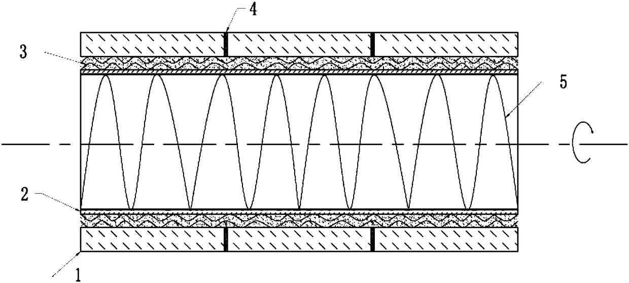
[0041] Such as figure 1 As shown, the Bang-type magnetron sputtering rotating target of the present invention includes a stainless steel back tube 1 and 12 AZO ceramic targets 3 fixedly sleeved on the outer wall of the stainless steel back tube 1, wherein both ends of the AZO target 3 are inverted C0.5 angle. The stainless steel back tube 1 and the AZO ceramic target 3 are connected by a sandwich structure 2 composed of a bonding material and a metal mesh sheet filled in the gap between the two. The inner wall of the AZO ceramic target 3 is connected to the outer wall of the stainless steel back tube 1 The gap is 0.35mm, and the target 3 and the target 3 are separated by a tetrafluoroethylene ring 4

[0042] Wherein, the metal mesh is a copper mesh.

[0043] Wherein, the bonding material is a graphene composite bonding material, which is composed of polymer resin and graphene in a mass ratio of 1.5:1.

[0044] Wherein, the polymer resin is a polyimide heterocycli...

Example Embodiment

[0052] Example 2

[0053] Such as figure 1 As shown, the Bang-type magnetron sputtering rotating target of the present invention includes a stainless steel back tube 1 and three TZO ceramic targets 3 fixedly sleeved on the outer wall of the stainless steel back tube 1, wherein the two ends of the TZO target 3 are inverted C0.5 angle. The stainless steel back tube 1 and the TZO ceramic target 3 are connected by a sandwich structure 2 composed of a bonding material and a metal mesh filled in the gap between the two. The inner wall of the TZO ceramic target 3 and the outer wall of the stainless steel back tube 1 The gap is 0.35 mm, and the target 3 and the target 3 are separated by a tetrafluoroethylene ring piece 4.

[0054] Wherein, the metal mesh sheet is an aluminum mesh sheet.

[0055] Wherein, the bonding material is a graphene composite bonding material, which is composed of polymer resin and graphene in a mass ratio of 1.5:1.

[0056] Wherein, the polymer resin is a polyimide ...

Example Embodiment

[0064] Example 3

[0065] Such as figure 1 As shown, the Bang-type magnetron sputtering rotating target of the present invention includes a stainless steel back tube 1 and five metal Ag targets 3 fixedly sleeved on the outer wall of the stainless steel back tube 1, wherein both ends of the Ag target 3 are inverted C1 corner. The stainless steel back tube 1 and the Ag target 3 are connected by a sandwich structure 2 composed of a bonding material and a metal mesh sheet filled in the gap between the two, and the gap between the inner wall of the Ag target 3 and the outer wall of the stainless steel back tube 1 is 0.35mm, the target 3 and the target 3 are separated by a tetrafluoroethylene ring sheet 4.

[0066] Wherein, the metal mesh sheet is an iron mesh sheet.

[0067] Wherein, the bonding material is a graphene composite bonding material, which is composed of polymer resin and graphene in a mass ratio of 2:1.

[0068] Wherein, the polymer resin is room temperature vulcanized sili...


PUM


Abstract

The invention relates to the technical field of sputtering target materials, in particular to a rotating target material capable of withstanding high-power sputtering. The rotating target material comprises a back tube and a section of target material which fixedly sleeves the outer wall of the back tube, wherein the back tube is connected with the target material by means of a sandwich structureformed by a bonding material and metal mesh pieces, and a gap between the back tube and the target material is internally filled with the bonding material. A preparation process of the target materialmainly comprises the four steps: (1) cleaning the back tube and the target material; (2) winding the metal mesh pieces on the back tube, and lining the inner surface of the target material with one layer of metal mesh pieces; (3) coating the surface of the back tube and the surfaces of inner holes of the target material with the bonding material, then sleeving the back tube with the target material from one end, and fixing; (4) curing the target material and the back tube subjected to sleeving so as to obtain the rotating target material. The rotating target material provided by the inventioncan withstand high-power sputtering, thus meeting the requirements of a high-power coating technology at present, and greatly increasing the coating efficiency.

Description

technical field [0001] The invention belongs to the technical field of sputtering targets, and relates to a bonding magnetron sputtering rotating target and a preparation method thereof, in particular to a rotating target capable of enduring high-power sputtering and a preparation method thereof. Background technique [0002] In 1842, Geboff discovered the phenomenon of cathode sputtering in the laboratory. Due to the lack of in-depth understanding of the sputtering mechanism and the slow development of sputtering thin film technology, commercial magnetron sputtering equipment was not gradually used in the laboratory until 1970. and small production. Since the 1980s, the electronics and information industry, which is dominated by integrated circuits, information storage, liquid crystal displays, laser memories, and electronic controllers, has entered a period of rapid development, and magnetron sputtering technology has truly entered industrial scale production from laborato...

Claims


Application Information

Patent Timeline
IPC IPC(8): C23C14/35C23C14/34
CPCC23C14/3407C23C14/35
Inventor 孔伟华
Owner 江苏迪丞光电材料有限公司
Why Eureka
Try Eureka