Washing machine

A technology for washing machines and washing tubs, applied in the field of washing machines, can solve the problems of limited location, increasing the rotating tub, limiting the volume of the rotating tub, etc., and achieves the effect of reducing the occupied space and reducing the inclination angle.

Pending Publication Date: 2018-09-25
QINGDAO HAIER WASHING MASCH CO LTD
View PDF7 Cites 2 Cited by
  • Summary
  • Abstract
  • Description
  • Claims
  • Application Information

AI Technical Summary

Problems solved by technology

[0004] The increase of the casing corresponding to the appearance of the washing machine is limited by the space of the area where the washing machine is installed. The location of the washing machine in the general user's home is limited. It is not realistic to increase the capacity of the washing bucket by adding the casing of the washing machine. For example, how On the premise of not increasing the casing of the washing machine, increasing the capacity of the rotating tub has become a major problem for designers
[0005] Suspended shock absorbers are generally installed between the rotating barrel and the casing to reduce the vibration of the rotating barrel, but the suspended shock absorbers are generally cable-stayed, which tends to occupy a large space between the rotating barrel and the casing. space, severely restricting the volume of the rotating barrel

Method used


Image

  • Washing machine
  • Washing machine
  • Washing machine

Examples


Embodiment 1

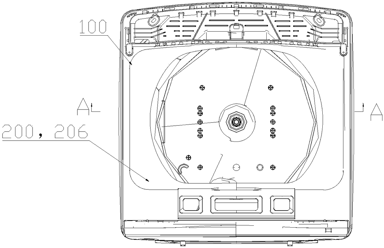
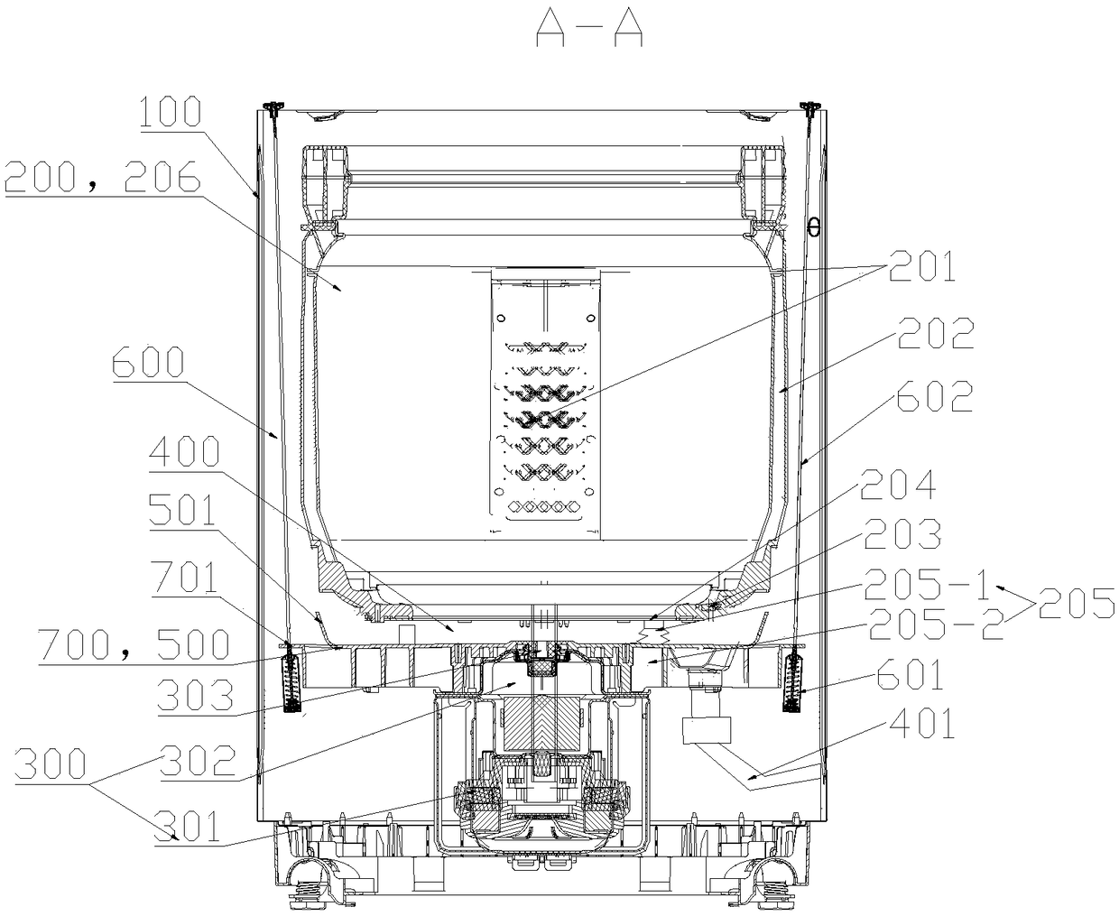
[0046] Such as Figure 1-3 As shown, a capacity-expanding washing machine with a water-retaining structure includes a box body 100, an inner tub 200 disposed in the box body 100, and a drive device 300 for driving the inner tub 200 to rotate, and also includes a drive device 300 for blocking water from the inner tub 200. A water-retaining structure for the overflow of discharged water. The water-retaining structure is located at the lower part of the bottom of the inner bucket 200 as a whole, and the inner bucket 200 has the function of holding water.

[0047]By setting the water retaining structure, on the one hand, when the water is discharged from the inner bucket 200, the water is blocked by the water retaining structure to prevent the water from overflowing; The partial structure between the side wall of the inner tub 200 and the box body 100 does not restrict the expansion of the inner tub 200 , and provides sufficient space for the expansion of the inner tub 200 .

[0...

Embodiment 2

[0055] Such as Figure 1-3 As shown, this embodiment is a further limitation of Embodiment 1. In this embodiment, the water retaining structure includes a mounting plate 500 and a water retaining rib 501 arranged on the mounting plate 500, and the mounting plate 500 and the water retaining The ribs 501 enclose the water collection cavity 400 . By arranging the installation plate 500 and the water retaining rib 501, and enclosing them to form the water collection cavity 400, the structure is simple and easy to process and shape.

[0056] The water collecting chamber 400 is located in the middle of the mounting plate 500, so that the center of gravity of the water retaining device can be more easily coincided with the center, and the offset can be reduced.

[0057] The water retaining rib 501 is ring-shaped, and the water retaining rib 501 and the installation plate 500 enclose to form a ring-shaped water collecting cavity 400 .

[0058] Further, the water retaining rib 501 is...

Embodiment 3

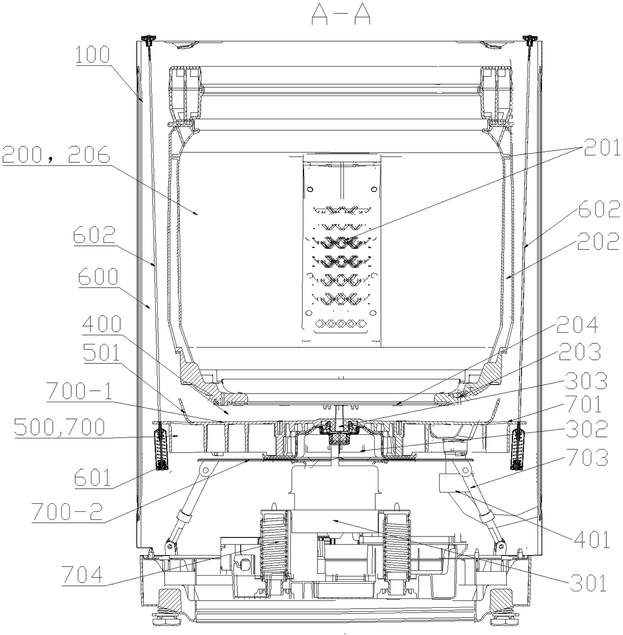
[0077] Such as Figure 1-2 As shown, a washing machine includes a box body 100, a washing bucket 206 disposed in the box body 100, and a driving device 300. The output shaft 303 of the driving device 300 is connected to the washing bucket 206 for driving the washing bucket 206 to rotate. It includes a suspension shock absorber 600 and a mounting part 700 arranged at the lower part of the washing tub 206, the driving device 300 is installed on the mounting part 700, one end of the suspension shock absorber 600 is connected with the box body 100, and the other One end is connected with the mounting part 700 .

[0078] By setting the mounting part 700 under the washing tub 206, the suspension shock absorber 600 is installed on the mounting part 700. Since the mounting part 700 is lower than the washing tub 206, the longitudinal height of the mounting part 701 is reduced, making the installation The inclination angle θ between the rear suspension shock absorber 600 and the box si...


PUM


Abstract

The invention belongs to the field of washing machines and particularly relates to a washing machine. The washing machine comprises a box body, a washing barrel and a driving device, wherein the washing barrel and the driving device are disposed in the box body; an output shaft of the driving device is connected with the washing barrel and used for driving the washing barrel to rotate. The washingmachine further comprises a suspending damping assembly and a mounting assembly disposed at the lower portion of the washing barrel; the driving device is mounted on the mounting assembly, one end ofthe suspending damping assembly is connected to the box body, and the other end of the suspending damping assembly is connected to the mounting assembly; by arranging the mounting assembly below thewashing barrel and mounting the suspending damping assembly on the mounting assembly, since the mounting assembly is lower than the washing barrel in position, the height of a mounting part is reduced, so that the tilting angle of the suspending damping assembly after installation is decreased, and correspondingly the occupied space of the suspending damping assembly is reduced. When the structureis suspended between the washing barrel and the box body, the purposes of increasing the diameter of the washing barrel and achieving volume expansion can be achieved under the premise of not increasing the size of the box body.

Description

technical field [0001] The invention belongs to the field of washing machines, and in particular relates to a washing machine. Background technique [0002] A washing machine is designed as a device for washing clothes by using electricity. In general, a washing machine includes: a tub for containing washing water; a rotary tub rotatably installed inside the tub; a pulsator rotatably installed in the rotary tub The bottom; motor and clutch, are configured to rotate the rotating barrel and pulsator. When the rotary tub and the pulsator rotate in a state that laundry and detergent are introduced into the rotary tub, the pulsator agitates wash water together with the laundry introduced into the rotary tub, thereby removing stains from the laundry. [0003] In order to increase the washing capacity of the washing machine, a larger rotary tub is required, that is, the height or diameter of the rotary tub needs to be increased. If the rotary tub has a larger size, the tub accomm...

Claims


Application Information

Patent Timeline
IPC IPC(8): D06F37/26D06F37/24
CPCD06F37/24D06F37/268D06F37/26
Inventor 许升劳春峰吕艳芬郝兴慧吴迪
Owner QINGDAO HAIER WASHING MASCH CO LTD
Why Eureka
Try Eureka