Construction equipment for building structure reinforcement

A technology for construction equipment and building structures, applied in building construction, construction, building maintenance, etc., can solve the problems of long time consumption, high labor intensity, time-consuming and laborious steel plate, etc., and achieve the effect of improving efficiency and reducing labor intensity.

Active Publication Date: 2018-09-25
中铁建设集团中南建设有限公司
View PDF9 Cites 10 Cited by
  • Summary
  • Abstract
  • Description
  • Claims
  • Application Information

AI Technical Summary

Problems solved by technology

[0003] In order to solve the above problems, the present invention provides a kind of construction equipment for building structure reinforcement, which can solve the problem of the need to manually transport steel plates in the existing process of bonding steel to strengthen buildings, and the need to manually coat the prepared glue on the steel plates. Paste the steel plate on the designated working surface. Manually conveying the steel plate is time-consuming and laborious. The irritating odor in the glue is harmful to human health. The artificial coating of glue is not uniform, which affects the effect of bonding steel to strengthen the building. The building working surface that needs to be reinforced The environment is complex, and there are potential safety hazards in the process of manual operation. It is cumbersome to manually vibrate and compact the pasted steel plates. The working range of manual pasted steel plates is limited, requiring frequent movement, poor stability, long time-consuming, high labor intensity and work efficiency. Low-level problems, it can realize the function of automatic construction of bonded steel reinforced buildings, without manual operation, there is no potential safety hazard, and it has the advantages of good stability, short time-consuming, simple operation, low labor intensity and high work efficiency.

Method used


Image

  • Construction equipment for building structure reinforcement
  • Construction equipment for building structure reinforcement
  • Construction equipment for building structure reinforcement

Examples


Embodiment Construction

[0031] In order to make it easy to understand the technical means, creative features, objectives and effects achieved by the present invention, the present invention will be further explained below in conjunction with specific drawings.

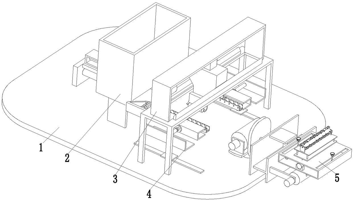
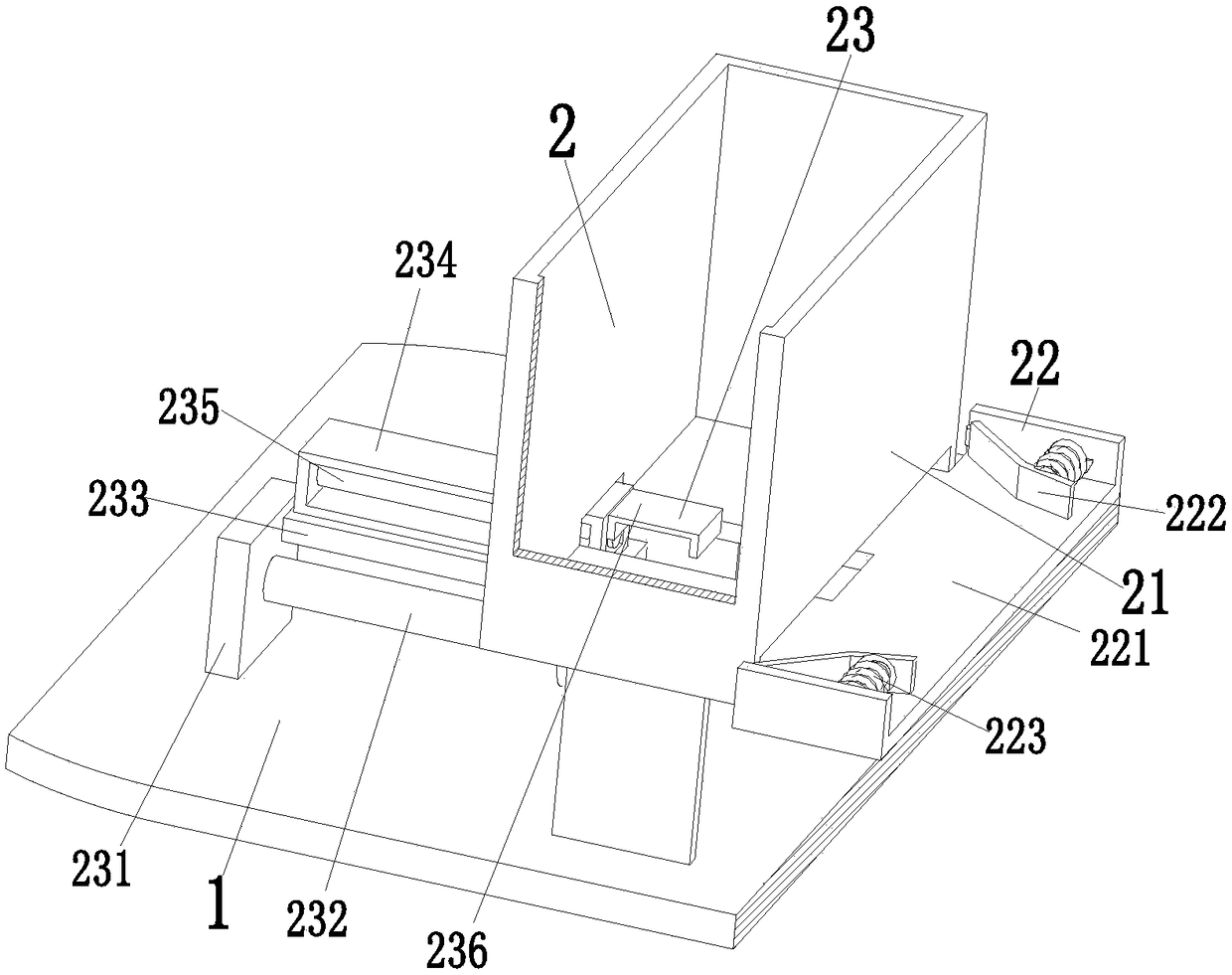
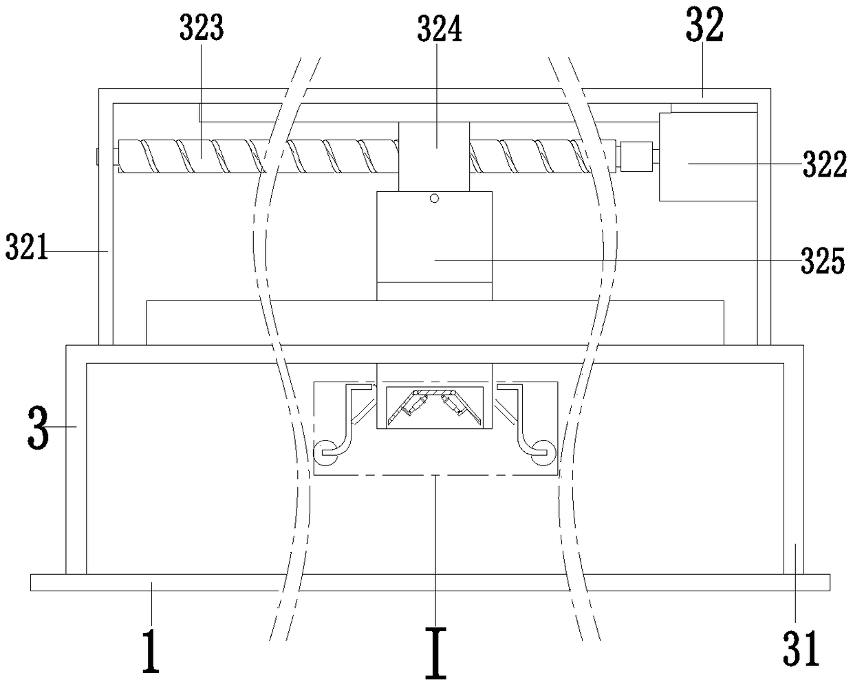
[0032] Such as Figure 1 to Figure 7 As shown, a construction equipment for building structure reinforcement includes a bottom plate 1, on which a conveying device 2, a gluing device 3, a fixing device 4, and a paving device 5 are sequentially installed from the front to the back, wherein the number of the fixing devices 4 is two, and The two fixing devices 4 are symmetrically located on the left and right sides of the bottom plate 1. The conveying device 2 conveys the steel plates one by one during work. The fixing device 4 fixes the steel plates during work. The glue application device 3 and the fixing device 4 cooperate with each other. The prepared glue is evenly coated on the steel plate, and the laying device 5 can lay the steel plate on t...


PUM


Abstract

The invention relates to construction equipment for building structure reinforcement. The construction equipment comprises a bottom plate, wherein a conveying device, a gluing device, two fixing devices and a laying device are sequentially installed on the bottom plate from front to back, and the two fixing devices are symmetrically located on the left side and the right side of the bottom plate.The problems that steel plates need to be transported manually, are coated with blended glue manually and are required to be bonded on designated working surfaces manually in the existing steel-bondedbuilding reinforcement process, manual transportation of the steel plates is time-consuming and strenuous, pungent odor in the glue is harmful to human health, the steel-bonded reinforcement effect on buildings is affected due to uneven manual application of the glue, potential safety hazards exist in the process of manual operation due to complex working environment of the to-be-reinforced building working surfaces, manual vibration compaction of the bonded steel plates is complicated, and frequent movement is required and stability is poor as a result of limited working range of manual bonding of the steel plates can be solved.

Description

Technical field [0001] The invention relates to the technical field of building structure reinforcement equipment, in particular to a building structure reinforcement construction equipment. Background technique [0002] Building reinforcement is the use of carbon fiber, bonded steel, and high-pressure grouting to strengthen the building. This technology is widely used in design changes, adding beams, columns, cantilever beams, slabs and other reinforcement and modification projects. It is a connection technology that uses structural glue for post-reinforcing steel reinforcement in seismic reinforcement of building structures. The method of sticking steel to strengthen buildings is currently widely used. When choosing sticking steel to strengthen buildings, it is necessary to apply glue to the surface of the sticking steel. Manually stick the steel plate coated with glue on the designated reinforcement position, but the existing sticking steel strengthens the building During the...

Claims


Application Information

Patent Timeline
Patent Type & Authority Applications(China)
IPC IPC(8): E04G23/02
CPCE04G23/0218
Inventor 潘岳燕
Owner 中铁建设集团中南建设有限公司
Why Eureka
Try Eureka