
Ferrite powder spraying and granulating device

A technology of spray granulation and ferrite, which is applied in the direction of liquid droplet granulation, iron compound, inorganic chemistry, etc., can solve the problems of low magnetic energy, poor granulation effect, low saturation magnetization, etc. High efficiency, improve granulation effect, and facilitate the effect of cyclic processing

Active Publication Date: 2018-09-28
济南高投能源发展有限公司
View PDF11 Cites 1 Cited by
  • Summary
  • Abstract
  • Description
  • Claims
  • Application Information

AI Technical Summary

Problems solved by technology

[0002] Ferrite is a metal oxide with ferromagnetism. In terms of electrical properties, the resistivity of ferrite is much larger than that of metal and alloy magnetic materials, and it also has high dielectric properties. Ferrite’s The magnetic performance also shows that it has a high magnetic permeability at high frequencies. Therefore, ferrite has become a non-metallic magnetic material that is widely used in the field of high-frequency and weak currents. Due to the low magnetic energy stored in the unit volume of ferrite, the saturation The magnetization is also low, which limits its application in low-frequency strong electricity and high-power fields that require higher magnetic energy density. When processing ferrite, it is sometimes necessary to process ferrite into powder spray, so iron needs to be Oxygen is processed into small particles. The existing granulation equipment is usually made by grinding, and the granulation effect is not good.

Method used


Image

  • Ferrite powder spraying and granulating device

Examples


Embodiment Construction

[0012] The following will clearly and completely describe the technical solutions in the embodiments of the present invention with reference to the accompanying drawings in the embodiments of the present invention. Obviously, the described embodiments are only some, not all, embodiments of the present invention. Based on the embodiments of the present invention, all other embodiments obtained by persons of ordinary skill in the art without making creative efforts belong to the protection scope of the present invention.

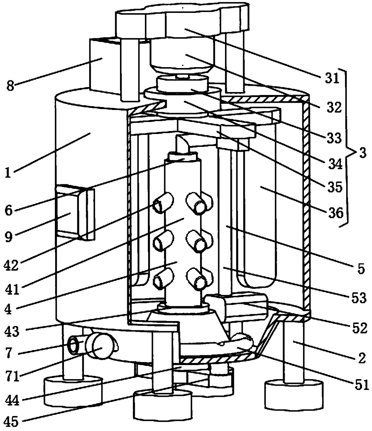
[0013] see figure 1 , the present invention provides a technical solution: a ferrite powder spray granulation device, including a barrel body 1, the lower surface of the barrel body 1 is provided with a pillar 2, there are four pillars 2, and the four pillars 2 are arranged on the barrel body The lower surface of 1 is evenly distributed, and the lower surface of the pillar 2 is provided with feet, which can improve the stability of the barrel body 1 and facili...


PUM


Abstract

The invention discloses a ferrite powder spraying and granulating device. The ferrite powder spraying and granulating device comprises a bucket body, wherein a support column is arranged at the lowersurface of the bucket body; a material charge hopper is arranged at the back end of the upper surface of the bucket body; a collision device is arranged at the upper end of the interior of the bucketbody; a material spraying device is arranged at the lower end of the interior of the bucket body; the lower end of the interior of the bucket body is provided with an annular groove; a material delivery device is arranged in the annular groove; an annular material suction pipe of the material delivery device is positioned at the lower end of the interior of the annular groove; a conveying pipe ofthe material delivery device is rotationally connected with the upper end of the inside surface of a sleeve cylinder through a third bearing; a material discharge pipe is arranged at the side surface,corresponding to the annular groove, of the bucket body. The ferrite powder spraying and granulating device has the advantages that the structure is simple, the ferrite can be sucked and conveyed, and the ferrite can be sprayed out at high speed; by utilizing the collision between the ferrites as well as between the ferrite and a collision plate, the particle size of the ferrite can be reduced, and the granulating effect is effectively improved; the operation is simple, and the working efficiency is high.

Description

technical field [0001] The invention relates to the technical field of ferrite processing, in particular to a ferrite powder spray granulation device. Background technique [0002] Ferrite is a metal oxide with ferromagnetism. In terms of electrical properties, the resistivity of ferrite is much larger than that of metal and alloy magnetic materials, and it also has high dielectric properties. Ferrite’s The magnetic performance also shows that it has a high magnetic permeability at high frequencies. Therefore, ferrite has become a non-metallic magnetic material that is widely used in the field of high-frequency and weak currents. Due to the low magnetic energy stored in the unit volume of ferrite, the saturation The magnetization is also low, which limits its application in low-frequency strong electricity and high-power fields that require higher magnetic energy density. When processing ferrite, it is sometimes necessary to process ferrite into powder spray, so iron needs t...

Claims


Application Information

Patent Timeline
Patent Type & Authority Applications(China)
IPC IPC(8): B01J2/04C01G49/00
CPCB01J2/04C01G49/0018
Inventor 孙海身张雷解传娣
Owner 济南高投能源发展有限公司
Learn More