Large-diameter counter bit machining method

A processing method and large-diameter technology, applied in the processing field of large-diameter countersinking, can solve the problems of large machining allowance, waste of machining time, and waste of tool materials, so as to ensure the processing quality, save tool processing materials, and improve processing efficiency effect

Inactive Publication Date: 2018-09-28
HARBIN TURBINE
View PDF7 Cites 0 Cited by
  • Summary
  • Abstract
  • Description
  • Claims
  • Application Information

AI Technical Summary

Problems solved by technology

[0004] The present invention provides a large-diameter countersinking processing method in order to solve the problems of wasting tool material, large machining allowance and wasting machining time in the existing large-diameter countersinking processing method.

Method used


Image

  • Large-diameter counter bit machining method
  • Large-diameter counter bit machining method
  • Large-diameter counter bit machining method

Examples


specific Embodiment approach 1

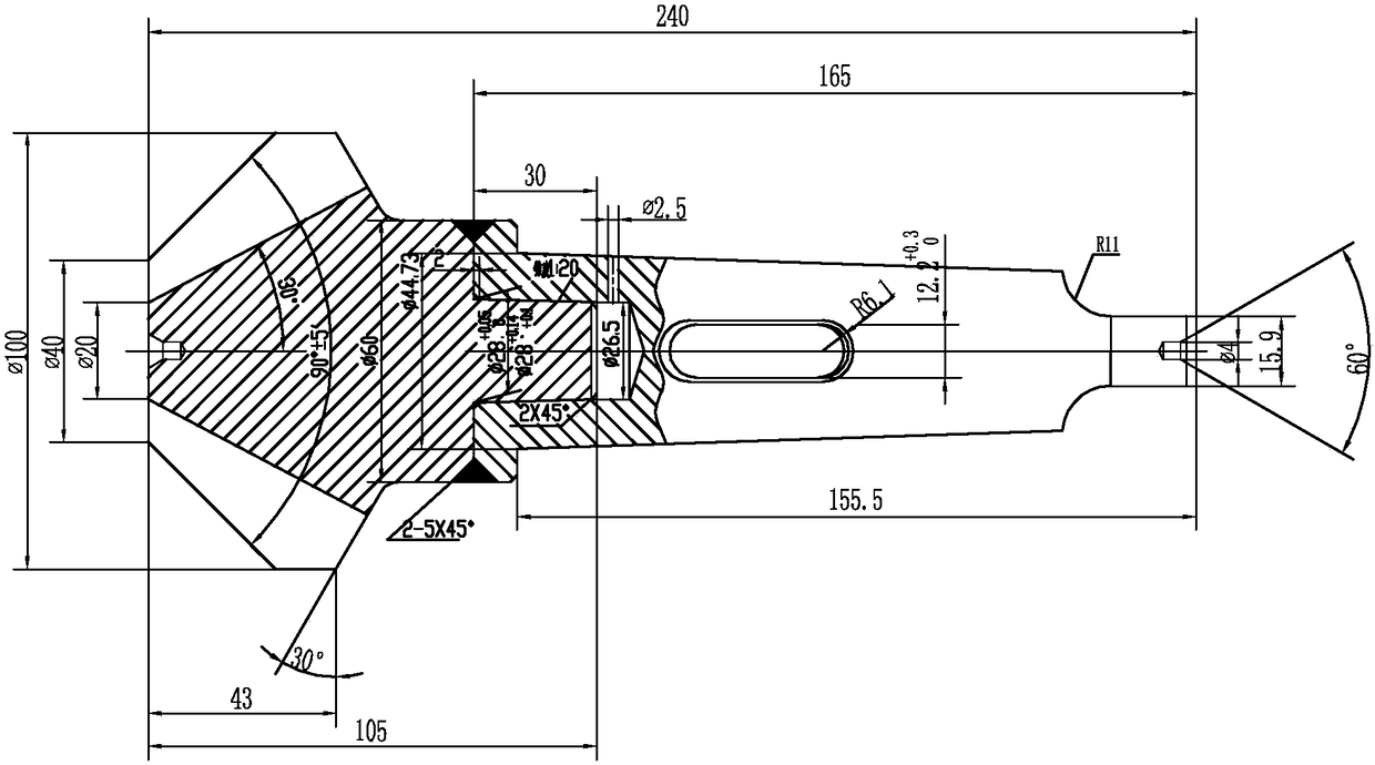
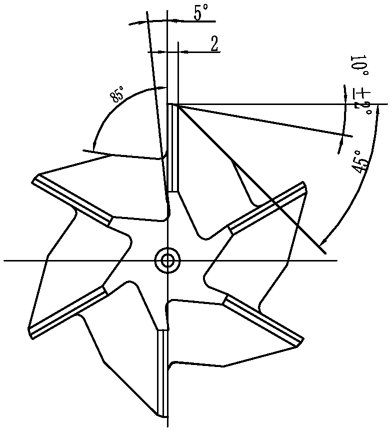
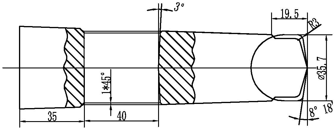
[0032] Specific implementation mode one: as Figure 1~3 As shown, the processing method steps of the large-diameter countersink of the present embodiment are as follows:

[0033] Step 1. Turning the countersink and the tool holder on the lathe: the tool holder adopts Mohs No. 5 taper shank, the taper of the taper shank is 0.6-0.7mm, the small end face of the tool holder is machined along the axial direction to the center hole, and the countersink is processed with a 90° conical surface , the volume of the taper surface is 0.6~0.7mm, the small end of the countersink drills the center hole along the axial direction, the taper of the large end of the countersink drill is turned into a 1:20 taper shank, and the large end of the tool bar is turned into a 1:20 taper hole, the taper The gap between the hole and the countersinking taper shank is 0.1mm, the taper hole is countersinked at 90° chamfering, and the outer circle of the countersinking drill and the tool holder is processed w...

specific Embodiment approach 2

[0045] Specific embodiment two: In this embodiment, the rotating speed is 240r / min, the feed rate is 0.3mm / r, and the cutting depth is 1.5mm. In this way, a small depth of cut of 1.5mm can be used for processing, which can effectively prevent the bending phenomenon of the processed parts and effectively ensure the quality of the processed surface. Other components and connections are the same as those in the first embodiment.

specific Embodiment approach 3

[0046] Specific implementation mode three: In step one of this implementation mode, the taper of the taper shank is increased to 0.65mm. In this way, a machining allowance is reserved. Other compositions and connections are the same as those in Embodiment 1 or 2.


PUM

PropertyMeasurementUnit
lengthaaaaaaaaaa

Abstract

The invention discloses a large-diameter counter bit machining method and relates to a counter bit machining method. By means of the large-diameter counter bit machining method, the problems that by means of an existing large-diameter counter bit machining method, tool materials are wasted, the machining allowance is extremely large, and machining time is wasted are solved. The large-diameter counter bit machining method comprises the steps that 1, a counter bit and a tool bar are turned through a lathe; 2, a counter bit groove, a front corner and a rear corner are milled through a horizontalmilling machine; 3, a tool bar flat tail is milled through the horizontal milling machine, and a tool bar kidney-shaped hole is milled; 4, a bench worker drills a vent hole communicating with a conical hole in the tool bar; 5, the counter bit and the tool bar are welded into a whole through electrowelding, and after welding, the welding stress is removed; 6, heat treatment is conducted on a 90-degree cutting conical surface, machined in step 1, of the counter bit till HRC66-68 is reached; 7, central holes in the two ends of the counter bit are ground; 8, the 5-degree front corner of the counter bit is ground through a tool grinding machine; 9, the central holes in the two ends of the counter bit are jacked through two jacking tips, the 90-degree cutting conical surface of the counter bit is ground, and a Mohs 5 taper-shank is ground; and 10, the 10-degree counter bit rear corner is ground through the tool grinding machine.

Description

technical field [0001] The invention relates to a processing method for a large-diameter countersink. Background technique [0002] At present, the chamfering of the positioning hole of the high-pressure cylinder is processed by a special countersink. The above-mentioned special countersink is a tool made of high-speed steel material. The machining allowance is huge, and the machining time is wasted. Therefore, it is necessary to develop a machining method for large-diameter countersinking. [0003] To sum up, using the existing large-diameter countersinking machining method wastes tool material, has a large machining allowance, and wastes machining time. Contents of the invention [0004] In order to solve the problems of wasting tool material, large machining allowance and waste of machining time in the existing large-diameter countersinking processing method, the invention further provides a large-diameter countersinking processing method. [0005] The technical schem...

Claims


Application Information

Patent Timeline
Patent Type & Authority Applications(China)
IPC IPC(8): B23P15/28
CPCB23P15/28
Inventor 魏成双缪佩珅陈家谊孙盛丽刘剑姜秀英岳云淼宋佳博
Owner HARBIN TURBINE
Why Eureka
Try Eureka