Automatic clamping device

A clamping device and automatic technology, which is applied in the direction of chucks, manipulators, manufacturing tools, etc., can solve the problems of low degree of automation, achieve the effect of optimizing the opening size, high angle positioning accuracy, and expanding the clamping range

Inactive Publication Date: 2018-09-28
李晓
View PDF0 Cites 0 Cited by
  • Summary
  • Abstract
  • Description
  • Claims
  • Application Information

AI Technical Summary

Problems solved by technology

[0004] The purpose of the present invention is to provide an automatic clamping device, which can achieve bidirectional clamping of the target object with only a single transmission component. At the same time, it can solve the problem of low automation of the existing clamping device When clamping, the workpiece can rotate freely around the axis of the rotating motor, and the workpiece can also swing left and right

Method used


Image

  • Automatic clamping device
  • Automatic clamping device

Examples


Embodiment Construction

[0022] In order to make the object, technical solution and advantages of the present invention more clear, the present invention will be further described in detail below in conjunction with the accompanying drawings.

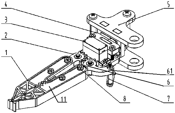
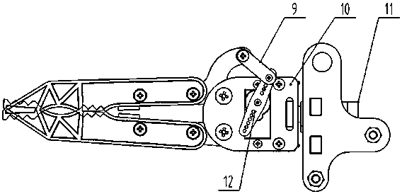
[0023] An automatic clamping device, the device includes left and right collets 1, 111, both of which are made of rubber. One end bolt 8 of 6 is connected, and the other end of the toothed handle 2 and the power transmission toothed handle 6 are respectively hingedly mounted on one end of the rotating motor fixture 10 and the teeth of the toothed handle 2 and the power transmission toothed handle 6 The shape heads are meshed with each other for transmission;

[0024] The other end side of the power transmission toothed handle 6 is bent outwards to form a rotating handle 61, the end of the horizontally arranged rotating handle 61 is fixedly connected with one end of the vertically placed vertical rod 7, and the vertically placed vertical rod 7 The other end of ...


PUM


Abstract

The invention belongs to the technical field of mechanical equipment and particularly relates to an automatic clamping device. Bidirectional clamping of a target object can be achieved just through asingle transmission component, meanwhile, the problem that the automation degree of existing clamping devices is low can be solved, when workpieces are clamped, the workpieces can do free rotation action in the circumferential direction of a rotary motor shaft, and the workpieces can swing left and right to rotate. The automatic clamping device is simple in structure and convenient to operate, andthe size of an opening can be adjusted.

Description

technical field [0001] The invention belongs to the technical field of mechanical equipment, in particular to an automatic clamping device. Background technique [0002] With the rapid development of my country's economy, my country has become the second largest economy in the world, and machining is a pillar industry in my country. In the process of machining, in order to improve production efficiency, automatic equipment is often used for production . [0003] The clamping device is the most common and frequently used equipment in machining, but the current clamping device is not highly automated, and when clamping the workpiece, it cannot perform free rotation in all directions, and cannot make the workpiece Carry out left and right rocking rotation, aim at the above-mentioned problem, be badly in need of carrying out technical innovation on the basis of existing clamping device. Contents of the invention [0004] The purpose of the present invention is to provide an a...

Claims


Application Information

Patent Timeline
Patent Type & Authority Applications(China)
IPC IPC(8): B25J15/02B25J15/08
CPCB25J15/02B25J15/08
Inventor 李晓李瑞江孟华张竹青
Owner 李晓
Why Eureka
Try Eureka