Heat insulation type concrete stirring system

A mixing system and concrete technology, applied in cement mixing devices, clay preparation devices, chemical instruments and methods, etc., can solve problems such as affecting building quality, long mixing time, reducing concrete performance, etc., achieving good temperature balance and improving mixing. performance, the effect of improving mixing efficiency

Active Publication Date: 2018-09-28
CHONGQING JIAOTONG UNIVERSITY
View PDF11 Cites 2 Cited by
  • Summary
  • Abstract
  • Description
  • Claims
  • Application Information

AI Technical Summary

Problems solved by technology

[0002] Concrete is a commonly used building material. Concrete is formed by mixing sand, cement, gravel and water. Concrete mixing is realized by a mixer. The existing concrete mixer has the following defects: during the concrete mixing process, the The concrete near the stirring paddle can be fully stirred, but the concrete far away from the stirring paddle cannot be fully stirred, especially the coagulation near the side wall of the container of the mixer, often deposits, which seriously affects the quality of the concrete ; Moreover, the existing agitator directly pours sand, cement and crushed stone into the mixing container, then adds water and then stirs. In this way, due to the fact that sand, crushed stone and cement are originally separated, the mixing time is long and the efficiency is low. Low; in addition, because the performance of concrete will be affected by temperature, the existing mixer can not maintain the temperature of concrete, especially in low temperature environment, the temperature is too low will lead to concrete freeze-thaw damage, thereby reducing the performance of concrete, seriously affecting the building quality

Method used


Image

  • Heat insulation type concrete stirring system
  • Heat insulation type concrete stirring system
  • Heat insulation type concrete stirring system

Examples


Embodiment Construction

[0035] Below in conjunction with accompanying drawing, the present invention is described in further detail, as shown in the figure:

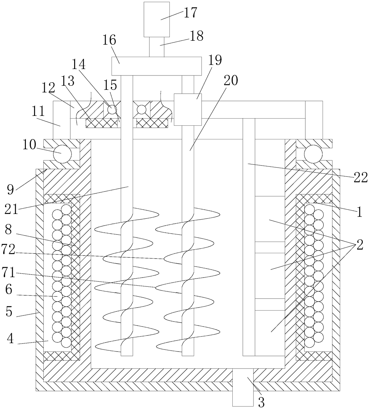
[0036] A thermal insulation concrete mixing system provided by the present invention includes a front-stage stirring device and a rear-stage stirring device;

[0037] The post-stage stirring device includes a post-stage mixing drum 1, a central agitator, a first planetary agitator, a second planetary agitator and a post-stage drive mechanism;

[0038] The outer sidewall of the rear-stage mixing drum 1 sinks along the radial direction of the rear-stage mixing drum 1 to form an annular groove 4, and a heating coil 6 is arranged in the annular groove 4, and the heating coil 6 and the groove wall of the annular groove 4 A heat-conducting insulating layer 8 is arranged between them, and an insulating heat-insulating cylinder 5 is also covered on the rear-stage mixing drum 1; wherein the heat-conducting insulating layer is made of an existing heat-co...


PUM


Abstract

The invention provides a heat insulation type concrete stirring system. The heat insulation type concrete stirring system comprises a front-stage stirring device and a rear-stage stirring device. Therear-stage stirring device comprises a rear-stage stirring barrel, a center stirrer, a first planet stirrer, a second planet stirrer and a rear-stage driving mechanism. The outer side wall of the rear-stage stirring barrel sinks in the radial direction of the rear-stage stirring barrel to form an annular groove, heating coils are arranged in the annular groove, a heat conducting insulating layer is arranged between the heating coils and the groove wall of the annular groove, and the stirring barrel is further sleeved with an insulating and heat insulating barrel. The front-stage stirring device comprises a front-stage stirring barrel, a front-stage stirring shaft and a front-stage driving device. Concrete in a stirring container can be fully stirred, the stirring efficiency can be effectively improved, and the timeliness of material supply is guaranteed. The concrete can be kept within a proper temperature range in a low-temperature environment, and the temperature balance of the concrete can be guaranteed.

Description

technical field [0001] The invention relates to a civil construction equipment, in particular to a thermal insulation concrete mixing system. Background technique [0002] Concrete is a commonly used building material. Concrete is formed by mixing sand, cement, gravel and water. Concrete mixing is realized by a mixer. The existing concrete mixer has the following defects: during the concrete mixing process, the The concrete near the stirring paddle can be fully stirred, but the concrete far away from the stirring paddle cannot be fully stirred, especially the coagulation near the side wall of the container of the mixer, often deposits, which seriously affects the quality of the concrete ; Moreover, the existing agitator directly pours sand, cement and crushed stone into the mixing container, then adds water and then stirs. In this way, due to the fact that sand, crushed stone and cement are originally separated, the mixing time is long and the efficiency is low. Low; in add...

Claims


Application Information

Patent Timeline
Patent Type & Authority Applications(China)
IPC IPC(8): B28C5/08B28C5/16
CPCB28C5/0806B28C5/0831B28C5/0875B28C5/16
Inventor 刘燕燕黄中文刘平周引
Owner CHONGQING JIAOTONG UNIVERSITY
Why Eureka
Try Eureka