3D printing head for material extrusion molding

A technology of extrusion molding and printing head, applied in the field of 3D printing, can solve the problems of unsatisfactory printing effect, clogged nozzle, affecting the precision and surface smoothness of parts, etc., to improve printing smooth performance, prevent material overflow, and optimize molding quality effect

Pending Publication Date: 2018-09-28
TIANJIN UNIV OF TECH & EDUCATION TEACHER DEV CENT OF CHINA VOCATIONAL TRAINING & GUIDANCE
View PDF6 Cites 4 Cited by
  • Summary
  • Abstract
  • Description
  • Claims
  • Application Information

AI Technical Summary

Problems solved by technology

[0003] However, the existing 3D printer nozzles are prone to wire breakage and nozzle blockage during the printing process. The efficiency of rapid prototyping is low and the printing effect is not ideal. The 3D printing nozzle itself performs multi-layer superposition on the forming surface. Problems and the sealing performance of the nozzle when it works intermittently are likely to cause wire drawing to block the nozzle, causing the 3D printer to malfunction, seriously affecting the accuracy and surface smoothness of the part

Method used


Image

  • 3D printing head for material extrusion molding
  • 3D printing head for material extrusion molding

Examples


Embodiment 1

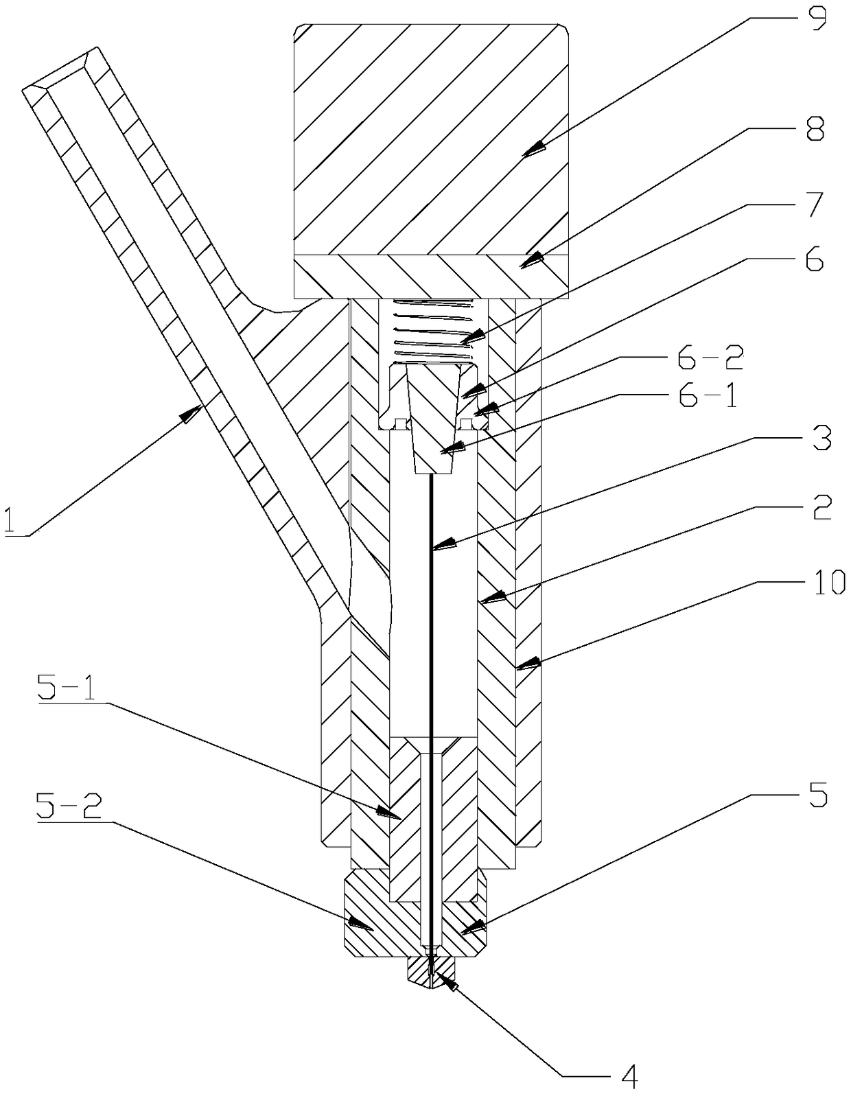
[0028] See attached figure 1 , a 3D printing head for material extrusion, including a wire feeding cavity 1, a thimble cavity 2, a sealing thimble 3, a printing nozzle 4, a heating module 5, a limit plug 6, a return spring 7, and an upper end cover 8 and electromagnet 9.

[0029] The thimble cavity 2 is vertically arranged, and the wire feeding cavity 1 is arranged on one side of the thimble cavity 2, and the wire feeding cavity 1 communicates with the thimble cavity 2 (the side wall of the thimble cavity is provided with a wire cavity outlet corresponding to the through hole), the heating module 5 is installed at the bottom of the thimble cavity 2, the heating module has a feeding inner channel, the bottom of the heating module is provided with the printing nozzle 4, the wire feeding cavity 1 , the thimble cavity 2, the inner channel of the heating module 5, and the printing nozzle 4 form a feeding channel.

[0030] The upper end cover 8 is installed on the top of the thimb...

Embodiment 2

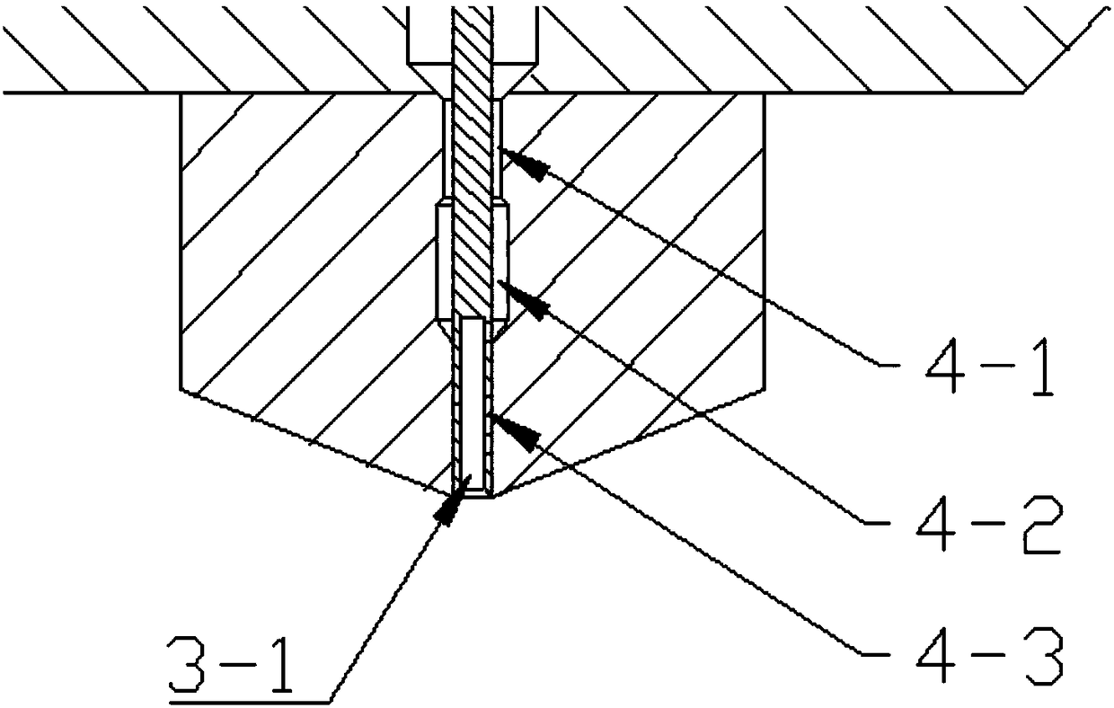
[0035] See attached figure 2Further, the discharge channel of the print nozzle 4 includes a first aperture section 4-1, a second aperture section 4-2 and a third aperture section 4-3 from top to bottom, and the diameter of the first aperture section is larger than The diameter of the sealing thimble, the diameter of the second aperture section is greater than the diameter of the first aperture section, and the diameter of the third aperture section is equal to the diameter of the sealing thimble; when the sealing thimble is pressed down, the molten material in the nozzle will Squeeze and squeeze to fill the second aperture section, and a part of the material will flow upward along the first aperture section (the diameter of the first aperture section is larger than the diameter of the sealing thimble), thereby reducing the amount of material extruded by the sealing thimble and preventing the formation of overflow drawing ; Finally, the third aperture section forms a seal with...

Embodiment 3

[0037] Further, the bottom of the sealing thimble 3 is provided with a section of hollow inner cavity 3-1, through which the hollow inner cavity further prevents material overflow: when the sealing thimble 3 is pressed down, the molten material in the nozzle will enter the sealing thimble 3 in the hollow cavity at the bottom, thereby effectively preventing the material from being extruded by the sealing thimble 3. After the sealing thimble 3 is lifted, the material in the hollow cavity of the sealing thimble 3 is heated to a molten state again, and drops from the hollow cavity.


PUM


Abstract

The invention discloses a 3D printing head for material extrusion molding. The 3D printing head comprises a wire feeding cavity, a thimble cavity, a sealing thimble, a printing nozzle, a heating module, a limiting plug, a return spring, an upper end cover and an electromagnet; the heating module is mounted at the bottom of the thimble cavity; the bottom of the heating module is the printing nozzle; the wire feeding cavity, the thimble cavity, an inner channel of the heating module and the printing nozzle form a feeding channel; the top of the thimble cavity is the upper end cover; the electromagnet is mounted on the upper end cover; the sealing thimble, the limiting plug and the return spring are all arranged in the thimble cavity; under the effects of the electromagnet and the return spring, the limiting plug can drive the sealing thimble to act up and down; when the electromagnet is electrified, the limiting plug drives the sealing thimble to lift to a high point, and at this time, the bottom end of the sealing thimble is deviated from the printing nozzle; and when the electromagnet loses power, the limiting plug drives the sealing thimble to descend to a low point under the effect of the return spring, and at this time, the bottom end of the sealing thimble blocks the printing nozzle to stop discharging.

Description

technical field [0001] The invention belongs to the technical field of 3D printing, and in particular relates to a 3D printing head for extruding materials. Background technique [0002] 3D printing technology refers to the fact that the print head performs material filling and manufacturing according to the cross-sectional information of the current layer under the control of the program, and then quickly manufactures the required parts through layer-by-layer accumulation. Because it can manufacture arbitrary complex parts and has better printing freedom It has more and more practical application value in industrial production and daily life. As an important branch of the field of 3D printing, 3D printing of extrudable materials has attracted more and more attention from scholars at home and abroad, because it has a wide range of materials that can be prepared, energy saving of some materials that can be recycled and remanufactured, and some light weight. Due to its high-s...

Claims


Application Information

Patent Timeline
Patent Type & Authority Applications(China)
IPC IPC(8): B29C64/209B29C64/30B33Y30/00B33Y40/00
CPCB29C64/209B29C64/30B33Y30/00B33Y40/00
Inventor 何永利李月辰张恩凤王文韬
Owner TIANJIN UNIV OF TECH & EDUCATION TEACHER DEV CENT OF CHINA VOCATIONAL TRAINING & GUIDANCE
Why Eureka
Try Eureka