Pressurized air underwater supply equipment and aerating system using same

A pressurized gas and equipment technology, which is applied in the field of equipment that transfers air to underwater, can solve the problems of easy damage, hinder development, and affect the popularization and application of small-scale sewage treatment equipment, and achieve the effect of low cost and easy maintenance

Pending Publication Date: 2018-09-28
曹军
View PDF0 Cites 0 Cited by
  • Summary
  • Abstract
  • Description
  • Claims
  • Application Information

AI Technical Summary

Problems solved by technology

[0006] First of all, most cheap low-power blowers are of poor quality and are easily damaged during use;
[0007] Secondly, the price of some low-power blowers is high, which often exceeds the cost requirements of small-scale SBR sewage treatment equipment users. People often exclude them directly from the perspective of cost, and prefer to choose cheap low-power blowers;
[0008] Third, when the blower breaks down, it needs the professional skills of special maintenance personnel to repair it, and rural individual farmers usually cannot repair it by themselves, so the maintenance cost of small-scale SBR sewage treatment equipment in rural areas is very high, which hinders this small-scale A factor in the development of SBR sewage treatment equipment
[0009] Fourth, due to the fixed power of the blower, the air supply can only be adjusted within a limited range, which cannot be flexibly applied to various scenarios, and cannot be flexibly adapted when the scale of sewage treatment changes
[0010] Due to the existence of the above problems, the huge market demand for small-scale sewage treatment in rural areas has been suppressed due to cost constraints, which has seriously affected the popularization and application of small-scale sewage treatment equipment in rural areas

Method used


Image

  • Pressurized air underwater supply equipment and aerating system using same
  • Pressurized air underwater supply equipment and aerating system using same
  • Pressurized air underwater supply equipment and aerating system using same

Examples


Embodiment Construction

[0057] In order to better explain the present invention and facilitate understanding, the present invention will be described in detail below through specific embodiments in conjunction with the accompanying drawings.

[0058] Pressurized gas underwater supply equipment

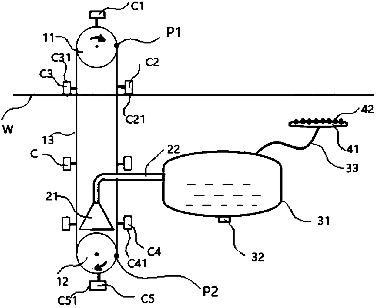
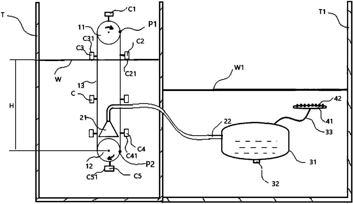
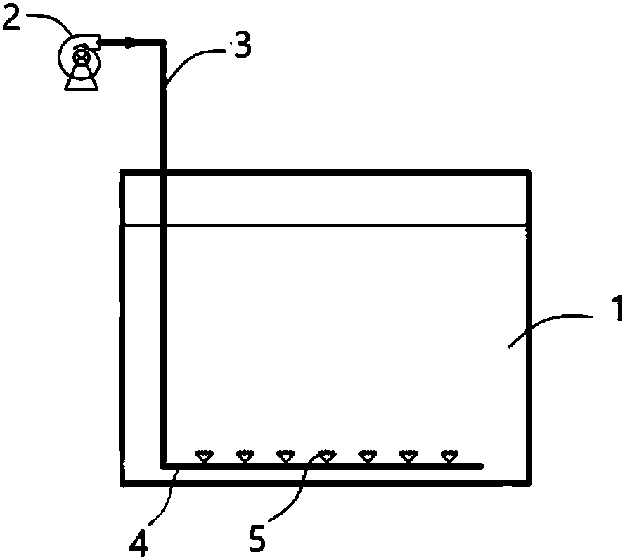
[0059] like figure 2 As shown, the pressurized gas underwater supply equipment of the present invention includes a gas transfer device for transferring air from above the water surface to underwater, and a gas collecting device and a gas storage buffer device for collecting the gas transferred underwater. further, figure 2 The pressurized gas underwater supply equipment is connected with the gas storage buffer device and the aeration device together image 3 The first aeration system shown, Figure 4 The second aeration system shown, the third underwater aeration system not shown. Going a step further, figure 2 The pressurized gas underwater supply equipment is connected with the aeration device to fo...


PUM


Abstract

The invention relates to pressurized air underwater supply equipment and an aerating system. The equipment comprises an air transferring device used for transferring air from the position above the water surface to the underwater position and an air collecting device used for collecting the air transferred to the underwater position, the air transferring device comprises a plurality of air transferring cups used for loading air. The aerating system further comprises an air storage buffer device and an aerating device used for aerating a reaction pool. The pressurized air underwater supply equipment can replace a draught fan, is low in cost, easy to maintain, flexible to use, can save energy and is environmentally friendly, can stably provide pressurized air sources, can adjust the air pressure by adjusting the liquid level, and can adjust the air flow by adjusting the number and the size of the air transferring cups and the revolving speed of a driving chain wheel, and thus underwaterair supply according to demands is achieved.

Description

technical field [0001] The present invention relates to an air conveying device, in particular to a device for transferring air underwater and its use. Background technique [0002] In the sewage treatment process, such as the process of using SBR sewage treatment equipment for sewage treatment, it is usually necessary to aerate underwater to promote the degradation reaction of pollutants. [0003] figure 1 It shows a common air transmission and aeration system in the prior art, which is used to aerate the reaction tank 1, wherein the blower 2 is connected with the air pipe 3 to supply air to the underwater aeration device. The power of the blower 2 is generally relatively large, and is suitable for providing air to multiple aeration pans 5 at the same time by means of the aeration branch pipe 4, so as to meet the aeration requirements of large-scale sewage treatment equipment. This equipment is usually suitable for large-scale treatment operations in sewage treatment plan...

Claims


Application Information

Patent Timeline
Patent Type & Authority Applications(China)
IPC IPC(8): C02F7/00C02F3/12
CPCC02F3/1263C02F3/1278C02F7/00C02F2301/066Y02W10/10
Inventor 曹军
Owner 曹军
Why Eureka
Try Eureka