Rotatable erection crane for assembling steel box girder

A steel box girder and rotary technology, which is applied in the field of traffic engineering, can solve the problems such as the inability to apply large-tonnage steel box girder, spanning valleys and flood areas, demanding ground conditions, and poor crane stability, so as to achieve a stable lifting process. High efficiency, high adaptability, and the effect of improving construction efficiency

Pending Publication Date: 2018-09-28
SHANDONG LUQIAO GROUP +1
View PDF6 Cites 6 Cited by
  • Summary
  • Abstract
  • Description
  • Claims
  • Application Information

AI Technical Summary

Problems solved by technology

The installation and construction of steel box girders of cable-stayed cable bridges in the prior art generally adopts two schemes: scheme 1 uses large-scale lifting equipment (floating crane or ground crane) to cooperate with bracket installation, this scheme is costly, requires harsh ground conditions and Large-scale lifting equipment site and tonnage conditions are limited and cannot be applied to the construction of large-tonnage steel box girders and projects across valleys and flood areas; plan 2 uses bridge deck cranes for cantilever assembly. This plan is safe, reliable, and economical. High efficiency, but the bridge deck crane in the prior art cannot rotate the steel box girder by 90°, and the stability of the crane walking process is poor, and there are certain safety hazards

Method used


Image

  • Rotatable erection crane for assembling steel box girder
  • Rotatable erection crane for assembling steel box girder
  • Rotatable erection crane for assembling steel box girder

Examples


Embodiment Construction

[0024] The preferred embodiments of the present invention will be described below in conjunction with the accompanying drawings. It should be understood that the preferred embodiments described here are only used to illustrate and explain the present invention, and are not intended to limit the present invention.

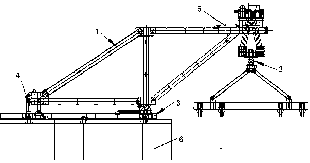
[0025] refer to figure 1 A rotatable deck crane for assembling steel box girders, comprising a walking system 3, a main truss system 1, a lifting system 2 and an anchoring system 4, the main truss system 1 is set on the installed steel box girder 6, the main The bottom of the truss system 1 is the walking system 2, and the upper part of the main truss system 1 is the hoisting system 2. There is a longitudinal adjustment system between the main truss system 1 and the hoisting system 2, and a slewing spreader 2-4 is installed on the hoisting system.

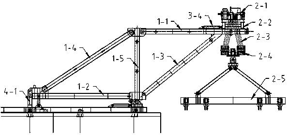
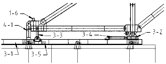
[0026] refer to figure 2 , image 3 , Figure 4 , the main truss system 1 includes two pairs of diamond-shaped tru...


PUM


Abstract

The invention provides a rotatable erection crane for assembling a steel box girder. Accurate assembling and butting after rotation of the steel box girder in a plane at 90 degrees in the air is realized. The rotatable erection crane for assembling the steel box girder comprises a walking system, a main truss system, a lifting system and an anchoring system, wherein the main truss system is arranged on the installed steel box girder, the walking system is arranged at the bottom of the main truss system, the lifting system is arranged at the upper part of the main truss system, a longitudinal movement adjustment system is arranged between the main truss system and the lifting system, and a rotatable lifting device is arranged on the lifting system. According to the preferred scheme of the rotatable erection crane for assembling the steel box girder, the walking system includes a pushing cylinder, a rail, a sliding seat and a reverse buckle mechanism, wherein the rail is arranged under the main truss system, the sliding seat matched with the rail is arranged on the rail, the sliding seat is connected to the front end of the pushing cylinder, the rail is connected to the rear end of the pushing cylinder, the upper part of the reverse buckle mechanism is mounted at the rear end of the main truss system through pin shafts, and the lower part of the reverse buckle mechanism is in contact with the outer side of a flange of the rail by rollers.

Description

technical field [0001] The invention relates to a bridge deck crane, in particular to a rotatable bridge deck crane for assembling steel box girders, which belongs to the technical field of traffic engineering. Background technique [0002] With the continuous development of bridge technology, the span of bridges continues to increase. Steel box girders are the first choice for long-span cable-stayed bridges due to their environmental protection, good economy, light weight, and good mechanical performance. The installation and construction of steel box girders of cable-stayed cable bridges in the prior art generally adopts two schemes: scheme 1 uses large-scale lifting equipment (floating crane or ground crane) to cooperate with bracket installation, this scheme is costly, requires harsh ground conditions and Large-scale lifting equipment site and tonnage conditions are limited and cannot be applied to the construction of large-tonnage steel box girders and projects across v...

Claims


Application Information

Patent Timeline
Patent Type & Authority Applications(China)
IPC IPC(8): E01D21/00B66C9/00B66C11/22
CPCE01D21/00B66C9/00B66C11/22
Inventor 王兴阔赵秋红白宾韩军霞李莹炜廖莹邢希瑞王殿学
Owner SHANDONG LUQIAO GROUP
Why Eureka
Try Eureka