Rotor pump

A rotor pump and rotor technology, which is applied to rotary piston pumps, pumps, pump components, etc., can solve the problems of cumbersome disassembly and assembly, high use and maintenance costs, and complex wear-resistant plate technology, so as to reduce replacement costs and prolong use. Effect of life and axial load reduction

Inactive Publication Date: 2018-09-28
奥戈恩(广州)泵业有限公司
View PDF5 Cites 2 Cited by
  • Summary
  • Abstract
  • Description
  • Claims
  • Application Information

AI Technical Summary

Problems solved by technology

However, this kind of wear-resistant plate has complicated process, cumbersome disassembly and assembly, and relatively high cost of use and maintenance. Generally, it is not widely used in the rotor pump for animal excrement cleaning.

Method used


Image

  • Rotor pump
  • Rotor pump
  • Rotor pump

Examples


Embodiment 1

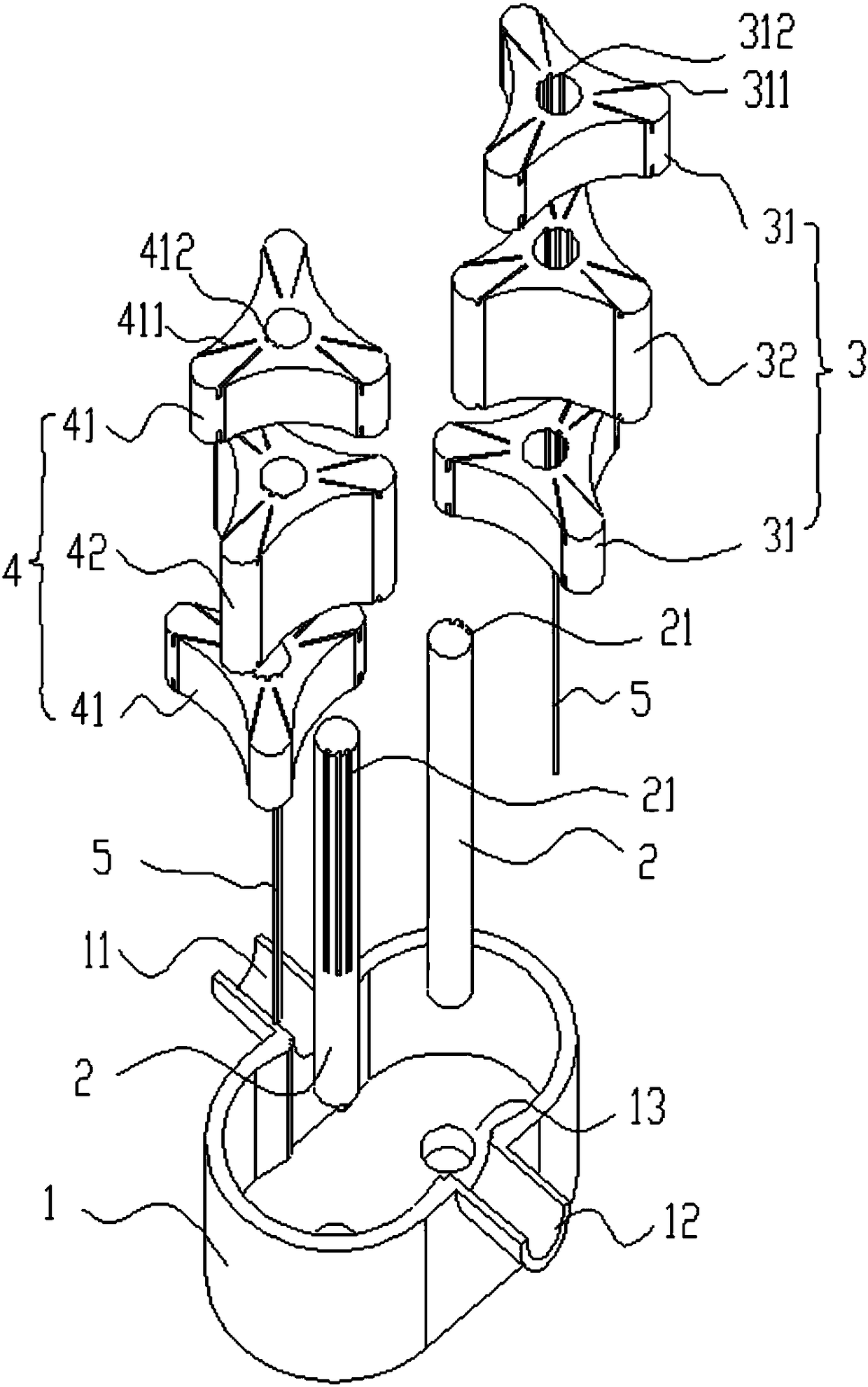
[0033] Such as figure 2 and image 3 As shown, when the rotor pump is applied in the case of high pressure difference and low viscosity fluid medium, multiple linear rotors of the driving rotor 3 and the driven rotor 4 are assembled with interleaving and equal phase difference, and each linear rotor is circumferentially symmetrical and has at least two blades , forming a symmetrical and uniform helical rotor structure.

[0034] The driving rotor 3 and the driven rotor 4 are engaged and installed in the pump body 1 according to the phase difference. When the driving rotor 3 drives the driven rotor 4 to rotate at high speed, the use effect of the helical rotor structure will be similar to that of the helical rotor pump. Compared with linear rotor pumps, screw rotor pumps have stable fluid medium pressure fluctuations.

[0035] In addition, due to the different thicknesses of multiple linear rotors, the relatively thick active linear rotor 2 32 faces the liquid inlet 11 and li...

Embodiment 2

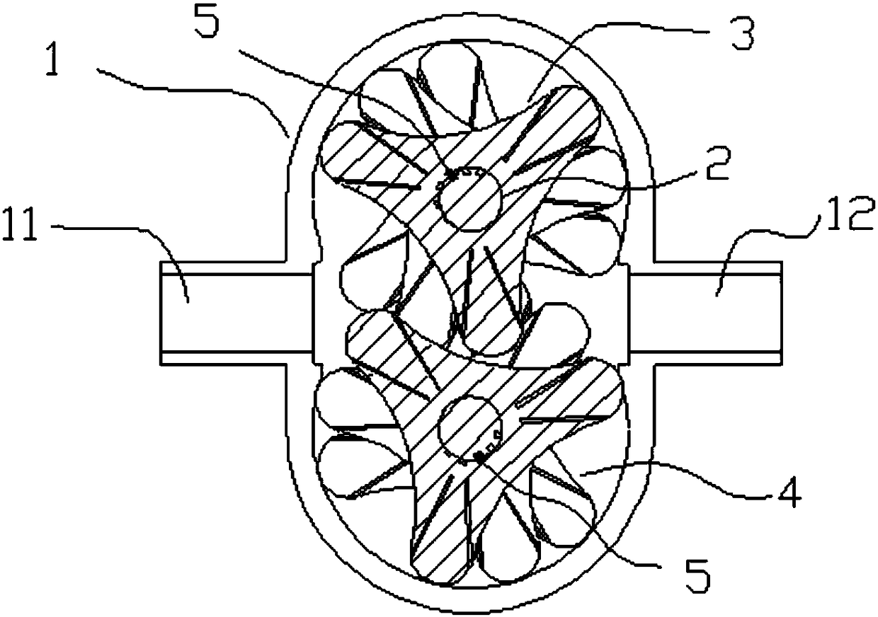
[0038] Such as Figure 4 and Figure 5As shown, when the rotor pump is applied in the case of low pressure difference and high viscosity fluid medium, multiple linear rotors of the driving rotor 3 and the driven rotor 4 are stacked and assembled, and each linear rotor is circumferentially symmetrical and has at least two blades to form a linear rotor. Rotor structure.

[0039] The driving rotor 3 and the driven rotor 4 are installed in the pump body 1 according to the phase difference. When the driving rotor 3 drives the driven rotor 4 to rotate at a low speed, the low-speed high-viscosity fluid is not sensitive to the pressure fluctuation of the fluid medium, and it is difficult to cause cavitation phenomenon without damaging the linear rotor structure.

[0040] In addition, due to the different thicknesses of the multiple linear rotors, the relatively thick active linear rotor 2 32 is facing the liquid inlet 11 and the liquid outlet 12 of the pump body 1, and the relativel...


PUM


Abstract

The invention discloses a rotor pump. The rotor pump comprises a pump body, a drive rotor, a driven rotor, connecting shafts and dowel pins, wherein the pump body is equipped with a liquid inlet and aliquid outlet; the liquid inlet and the liquid outlet are at the same height, and are isolated by the drive rotor and the driven rotor; the two connecting shafts are separately mounted in two rotaryshaft through holes of the pump body, and are separately fixed with the drive rotor and the driven rotor through the dowel pins; and the drive rotor or the driven rotor is formed by alternatively assembling a plurality of linear rotors. According to the rotor pump disclosed by the invention, the linear rotors are alternatively assembled, and rotor blade grooves are alternatively designed, so thatthe defect that a conventional rotor pump is limited in application and is high in using and maintaining cost is solved, and therefore, using and maintain cost is reduced, the pump body structure is not replaced and changed, and labor power and equipment expenditure are saved.

Description

technical field [0001] The invention belongs to the field of fluid machinery, and in particular relates to a rotor pump. Background technique [0002] The existing rotor pump consists of a stationary pump casing and a rotating rotor. After the liquid flows in through the liquid inlet of the pump casing, the master and slave rotors squeeze each other and rotate, forming a negative pressure at the extrusion point, and the negative pressure pumps the liquid from the liquid inlet. , and under the squeeze action of the rotor, the liquid is discharged from the pump casing drain port. Due to the continuous rotation of the rotor, a pressure difference is formed between the liquid inlet and the liquid outlet, and the liquid inlet is in a state of negative pressure, so the liquid flows in continuously from the liquid inlet. The main component of the rotor pump is the rotor, and the service life of the rotor directly determines the performance of the rotor pump. [0003] In the case ...

Claims


Application Information

Patent Timeline
IPC IPC(8): F04C2/14F04C15/00
CPCF04C2/14F04C15/00F04C2240/20
Inventor 汤仁亮
Owner 奥戈恩(广州)泵业有限公司
Why Eureka
Try Eureka