Self-locking large and small flow intelligent detection control equipment

A technology of intelligent detection and control equipment, applied in the direction of mechanical equipment, lifting valves, valve details, etc., can solve the problems of inaccurate monitoring of flow, inconvenient signal transmission, unstable monitoring results, etc., to achieve stable and reliable flow monitoring, Improve the scope of use, signal processing simple and stable effect

Active Publication Date: 2018-09-28
湖南欧柏测控系统有限责任公司 +3
View PDF11 Cites 1 Cited by
  • Summary
  • Abstract
  • Description
  • Claims
  • Application Information

AI Technical Summary

Problems solved by technology

The current water flow monitoring meters all use traditional flow meters or flow water meters, but there is a defect in the existing flow meters or flow water meters. When the flow in the pipeline fluctuates greatly, it is limited to the existing flow meter impeller structure. As a result, the flow cannot be accurately monitored, making the measurement results inaccurate
At present, in order to solve this problem, a bypass branch is installed on the pipeline, a large flow meter and an electric control valve are installed on the main pipe, and a small flow meter and an electric control valve are installed on the bypass branch, and then flow meters of different sizes are used to cooperate. The solenoid valve controls the electric control valve to open the main pipe or the bypass branch pipe according to the flow rate to realize accurate flow monitoring. This method not only complicates the pipeline setting, but also has high cost. At the same time, due to the increase of electronic control equipment parts, the circuit stability is poor and the monitoring results are also poor. Unstable and prone to failure; and the existing water flow control is generally achieved through the flow meter to detect the flow, in addition, it is necessary to use other supporting water circuit electric control valves to realize the opening and closing of the water circuit, due to the flow meter and electronic control The valves are located in different positions of the pipeline, the signal transmission is inconvenient, the installation is also relatively complicated, the cost is high, and the control is unstable

Method used


Image

  • Self-locking large and small flow intelligent detection control equipment
  • Self-locking large and small flow intelligent detection control equipment
  • Self-locking large and small flow intelligent detection control equipment

Examples


Embodiment Construction

[0032] In order to enable those skilled in the art to better understand the technical solution of the present invention, the present invention will be described in detail below in conjunction with the accompanying drawings. The description in this part is only exemplary and explanatory, and should not have any limiting effect on the protection scope of the present invention. .

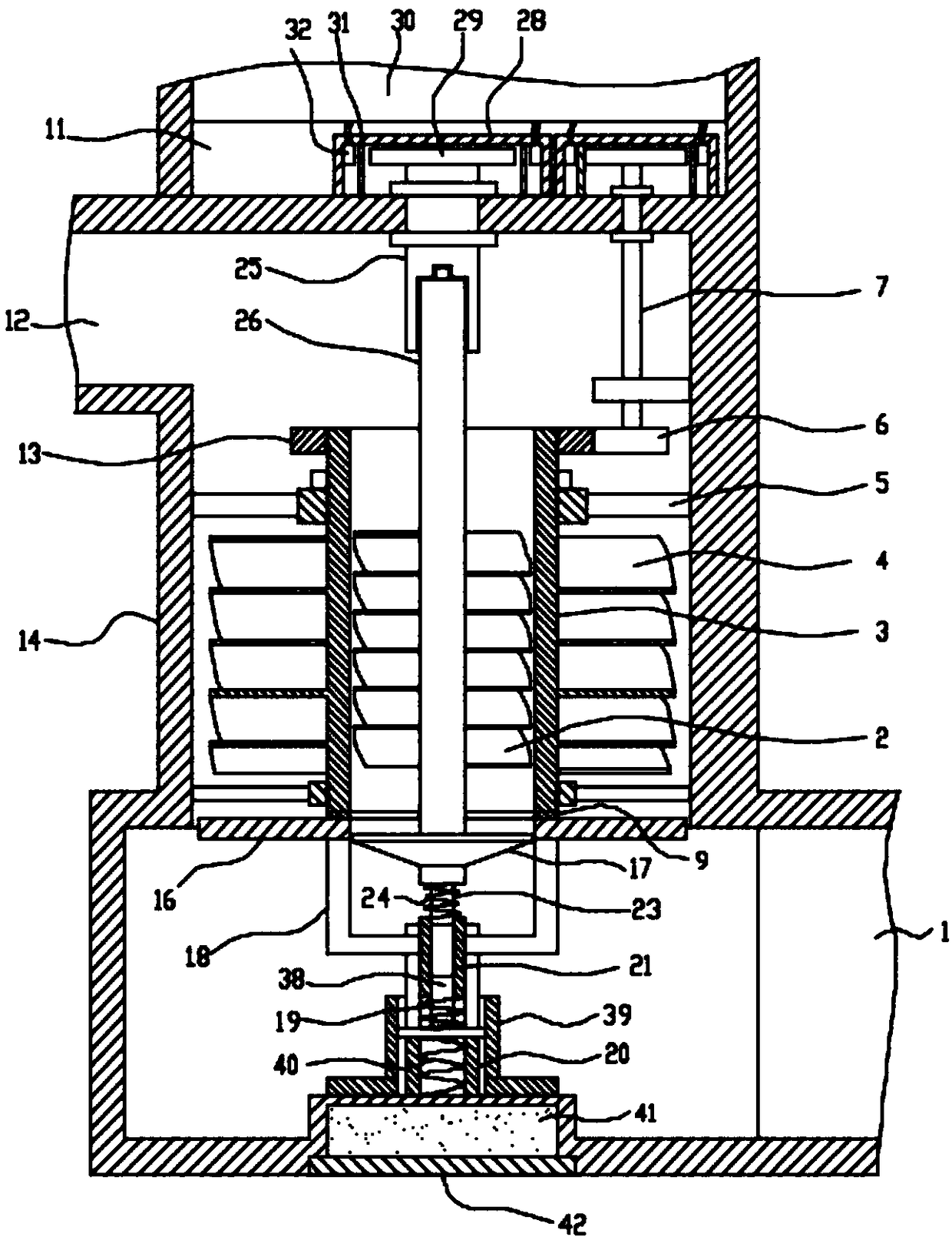
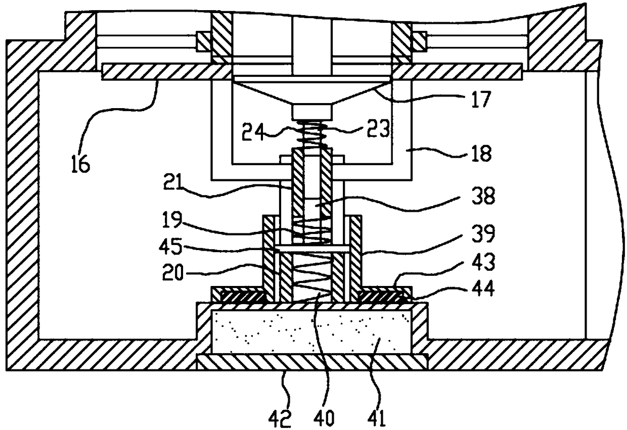
[0033] Such as Figure 1-Figure 13 As shown, the specific structure of the present invention is: a self-locking intelligent detection and control device for large and small flows, which includes an installation cavity 14, the top side of the installation cavity 14 is provided with a water inlet 12, and the bottom side is provided with a water outlet 1 , the outer impeller 4 is vertically arranged in the installation cavity 14; the center of the outer impeller 4 is provided with a sleeve shaft 3; the inner impeller 2 is coaxially arranged in the sleeve shaft 3; the lower end of the sleeve shaft 3 The l...


PUM


Abstract

The invention discloses self-locking large and small flow intelligent detection control equipment. An outer impeller is arranged in a mounting cavity; a bush shaft is arranged at the center of the outer impeller; an inner impeller is arranged in the bush shaft; a rotating shaft is arranged at the center of the inner impeller; the top end of the rotating shaft is connected to a first transmission shaft through a spline structure; a water plugging cover is arranged at the lower end of the rotating shaft; a fine shaft is arranged at the lower end of the water plugging cover; the lower end of thefine shaft is connected in a lifting barrel in a sleeved manner; a water plugging ring is arranged in the bottom of the outer impeller; a bottom gear ring is arranged on the upper end surface of the water plugging ring; the lifting barrel is arranged in the fixed barrel; a slot is formed in the outer wall of the fixed barrel; a lifting cover is connected to the lower end of the fixed barrel in a sleeving manner; a jacking shaft is arranged at the center of the lifting cover; the jacking shaft is connected in the lifting barrel in a sleeved manner; a locking spring is arranged at the lower endof the jacking shaft; a magnetic conductive plate is arranged at the lower end of the lifting cover; and an electromagnet is arranged in the bottom of a mounting cavity. The self-locking large and small flow intelligent detection control equipment disclosed by the invention not only can monitor water flows of different sizes, but also can lock open and close of a water path, and is high in detection precision and stable and reliable to operate.

Description

technical field [0001] The invention relates to the technical field of intelligent monitoring instruments, in particular to a self-locking type intelligent detection and control equipment for large and small flows. Background technique [0002] Smart instrumentation refers to instruments and instruments used in discrete manufacturing and process industry equipment to continuously measure variables such as temperature, pressure, flow, and level, or to measure physical parameters such as object position, tilt, and rotation, as well as material composition. Including sensors and their systems, intelligent temperature, pressure, flow, level measuring instruments, smart meters, smart water meters, and other monitoring devices. The current water flow monitoring meters all use traditional flow meters or flow water meters, but there is a defect in the existing flow meters or flow water meters. When the flow in the pipeline fluctuates greatly, it is limited to the existing flow meter...

Claims


Application Information

Patent Timeline
Patent Type & Authority Applications(China)
IPC IPC(8): F16K37/00F16K31/06F16K1/00
CPCF16K1/00F16K31/06F16K37/005
Inventor 刘开丽许翠芳张立俊廖长安
Owner 湖南欧柏测控系统有限责任公司
Why Eureka
Try Eureka