Ship radar system on basis of network transmission

A marine radar and network transmission technology, applied in the direction of radio wave measurement systems, instruments, etc., can solve problems such as mutual interference, difficulties, signal attenuation and installation, and achieve the effects of improving reliability, high echo restoration, and reducing requirements

Inactive Publication Date: 2018-09-28
NANJING JUNLU TECH
View PDF5 Cites 1 Cited by
  • Summary
  • Abstract
  • Description
  • Claims
  • Application Information

AI Technical Summary

Problems solved by technology

[0005] The transceiver and the host display are generally placed outside and indoor of the ship respectively. So many data and control signals are transmitted through cables, there are problems such as mutual interference, excessive signal attenuation during transmission, and installation difficulties.

Method used


Image

  • Ship radar system on basis of network transmission
  • Ship radar system on basis of network transmission
  • Ship radar system on basis of network transmission

Examples


Embodiment Construction

[0036] In order to make the purpose, technical solutions and advantages of the embodiments of the present invention clearer, the technical solutions in the embodiments of the present invention will be clearly and completely described below in conjunction with the drawings in the embodiments of the present invention. Obviously, the described embodiments It is a part of the embodiments of the present invention, rather than all embodiments; based on the embodiments of the present invention, all other embodiments obtained by those of ordinary skill in the art without creative work, all belong to the protection scope of the present invention .

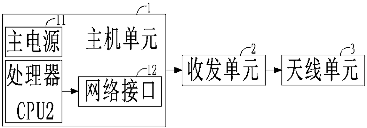
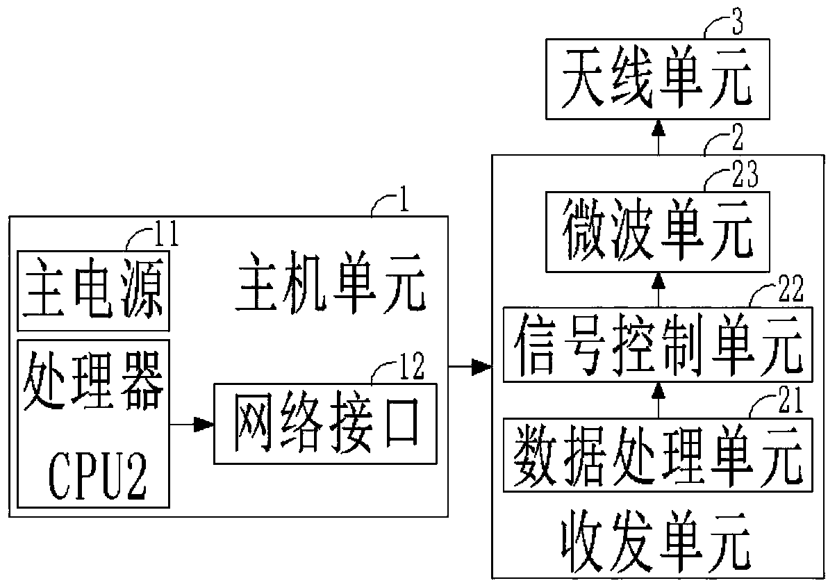
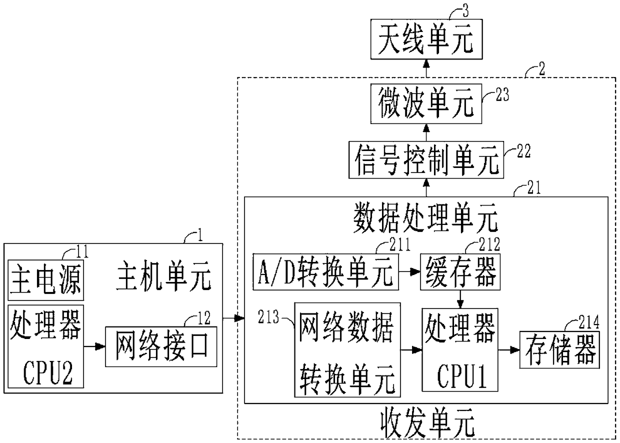
[0037] figure 1 A schematic structural diagram of a network-based marine radar system provided in Embodiment 1 of the present invention, as shown in figure 1 As shown, a network-based marine radar system includes:

[0038] Host unit 1: installed in the cab, used to control the radar; through the host unit 1, the user can directly control ...


PUM


Abstract

The invention discloses a ship radar system on the basis of network transmission. The ship radar system comprises a host unit, a receiving and transmitting unit and an antenna unit. The host unit is mounted in a cab and is used for controlling radar; the receiving and transmitting unit is mounted at a high location outside a ship, is electrically connected with the host unit and is used for carrying out data interaction with the host unit; the antenna unit is mounted at a high location outside the ship, is electrically connected with the receiving and transmitting unit and is used for transmitting electromagnetic waves and receiving echo signals from target objects. The ship radar system has the advantages that the requirements of the host unit on the computation speeds of devices can be lowered, accordingly, pictures are smooth, and echo picture details are easy to present; software and hardware platforms can be provided to multi-radar networked management by the aid of network transmission.

Description

technical field [0001] The invention belongs to the technical field of marine radar, in particular to a marine radar system based on network transmission. Background technique [0002] Marine radar works in the microwave band, mainly X-band or S-band, and the frequency is very high. The power microwave emitted from the antenna returns to the receiving antenna after being reflected by the measured target, and then the useful target signal is picked up through tuning and mixing. The echo signal is processed by the back end to form a graphic displayed to the user, or other signal forms required by the user. [0003] Usually, there is a division of labor between the radar transceiver and the host display. The transceiver receives the power-on and other control signals of the host display, and is mainly responsible for forming high-power microwave transmission, antenna scanning, receiving echoes and processing them into video signals to send to the host display. The host display...

Claims


Application Information

Patent Timeline
Patent Type & Authority Applications(China)
IPC IPC(8): G01S7/02
CPCG01S7/02
Inventor 徐俊杰林毓平
Owner NANJING JUNLU TECH
Why Eureka
Try Eureka