
Target object motion monitoring system and method

A motion monitoring and target technology, which is applied in the field of target recognition and motion monitoring systems, can solve the problems of being susceptible to interference, target impact, increasing equipment installation workload and equipment investment cost, etc., to increase versatility and reduce complexity The effect of reducing the limit of application scenarios

Pending Publication Date: 2018-09-28
CATHAY NEBULA SCI & TECH CO LTD
View PDF0 Cites 21 Cited by
  • Summary
  • Abstract
  • Description
  • Claims
  • Application Information

AI Technical Summary

Problems solved by technology

[0006] The installation method of the contact monitoring method determines the uniqueness of its measurement target, that is, a monitoring system can only monitor one target that is fixed to it, and it cannot realize the measurement of multiple targets, and the function is single
Therefore, for the measurement application of multiple targets, multiple monitoring systems need to be completed together, which virtually increases the workload of equipment installation and equipment investment cost.
Especially for vehicle, container monitoring and other application scenarios that need to change targets frequently, the contact monitoring method is even more difficult to complete
[0007] 2. have an impact on the target
[0010] The power supply and communication of the contact monitoring system are another important factor restricting its application. The use of cable communication will restrict the range of motion of the target, while the use of wireless communication methods is susceptible to interference and may also have a potential impact on the work of the target; The power supply problem of the contact monitoring system also puts forward more restrictions on its application scenarios and target types

Method used


Image

  • Target object motion monitoring system and method
  • Target object motion monitoring system and method
  • Target object motion monitoring system and method

Examples


Embodiment Construction

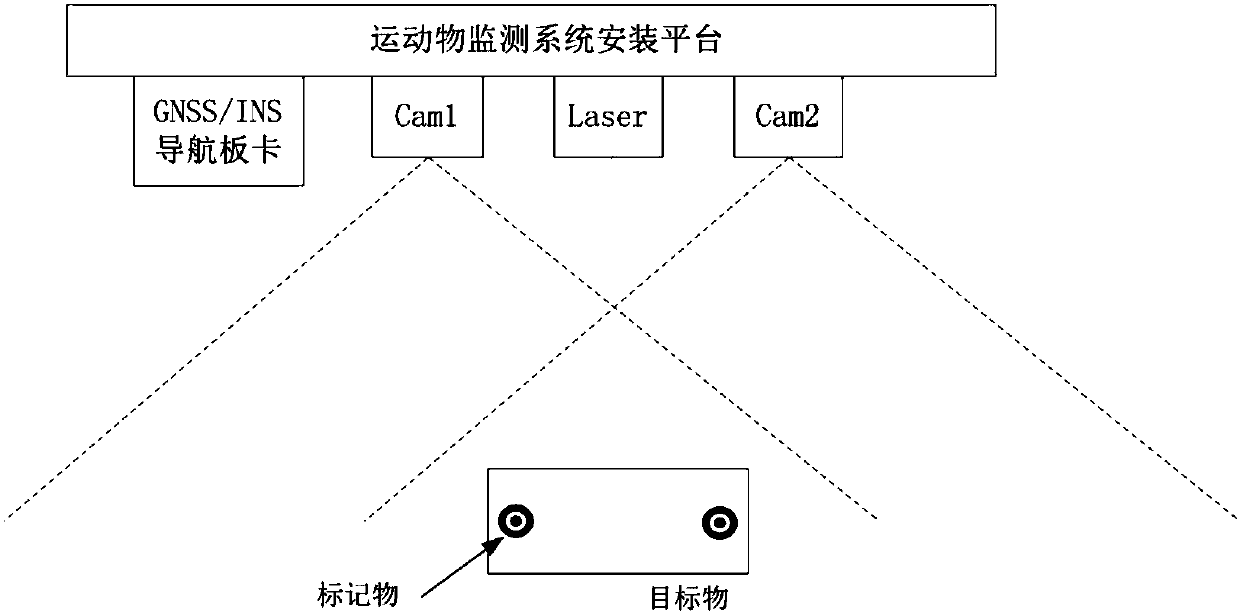
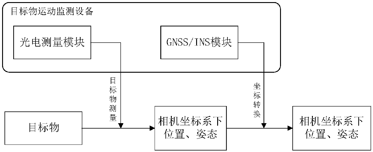
[0030] The target movement monitoring system consists of two modules: photoelectric measurement module and GNSS / INS integrated navigation module. The relative installation position relationship of each module of the system is as attached figure 1 As shown, the photoelectric measurement module is composed of two high-speed cameras (constituting a binocular camera) and a 3D laser radar, and the three are arranged in a line, and jointly identify and measure the target within a certain range in front of the camera; GNSS / INS integrated navigation module and photoelectric measurement module are installed on the target motion monitoring platform to provide real-time position and attitude reference information of the target motion monitoring system.

[0031] Since there are inevitably installation errors during the system installation process, and the relative conversion relationship between the laser radar, camera and GNSS / INS and other equipment is unknown, the graphic distortion o...


PUM


Abstract

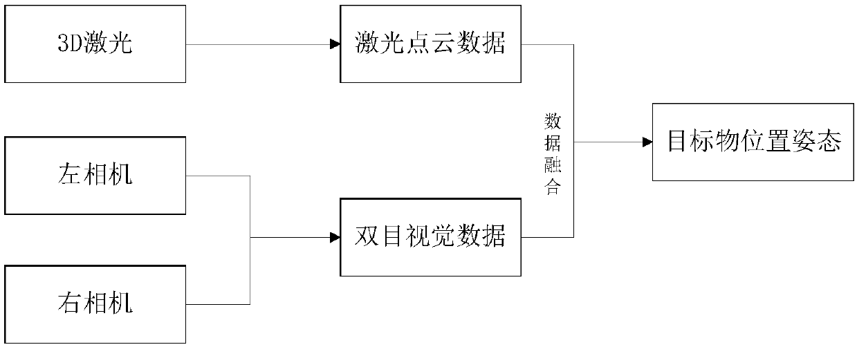
The invention discloses a target object motion monitoring system and method. The monitoring system comprises an industrial personal computer, a binocular camera, a 3D laser scanner and a GNSS / INS combined navigation module, and the industrial personal computer is connected with the binocular camera, the 3D laser scanner and the GNSS / INS combined navigation module and used for fusion processing ofbinocular visual data, laser point cloud data and measurement data of the GNSS / INS combined navigation module and real-time providing of relative position and posture of a target relative to the camera and absolute position and posture of the target relative to the ground. The target object motion monitoring system and method has advantages that noncontact recognition and measurement of the targetare realized, and accordingly application scene limitation is greatly lowered, and universality in target motion monitoring is improved; further, due to noncontact measurement, influences on the monitoring system on normal operation of the target are greatly reduced; in addition, the system does not move along with the target and is insusceptible to cable power supply or wireless communication, so that complexity in system mounting is greatly reduced while stability in operation is improved.

Description

technical field [0001] The invention relates to a target recognition and motion monitoring system and method based on laser, binocular vision and GNSS / INS, which can realize intelligent recognition of targets and accurate perception and monitoring of positions and attitudes. Background technique [0002] Target recognition and motion monitoring technology can identify the target and perceive the trajectory and posture of the target. It is an important method to grasp the real-time motion state of the target and is also the direct basis for the motion control of the target. At present, the commonly used means of target motion monitoring are target position perception and attitude measurement. [0003] According to the relative positional relationship between the detection system and the target, motion monitoring methods are divided into contact and non-contact. [0004] At present, most of the target motion monitoring methods are contact methods, that is, the measurement sys...

Claims


Application Information

Patent Timeline
IPC IPC(8): G01S17/02G01S17/50G01S19/47G01S19/45G01S19/53
CPCG01S17/50G01S19/45G01S19/47G01S19/53G01S17/86
Inventor 徐广鹏张桂琴候利朋冯丙岩
Owner CATHAY NEBULA SCI & TECH CO LTD
Learn More