
Heat dissipation type power equipment box

A power equipment box, heat dissipation technology, applied in electrical components, substation/distribution device housing, substation/switch layout details, etc. speed, the effect that is conducive to safe and stable operation

Inactive Publication Date: 2018-09-28
张宝泽
View PDF5 Cites 7 Cited by
  • Summary
  • Abstract
  • Description
  • Claims
  • Application Information

AI Technical Summary

Problems solved by technology

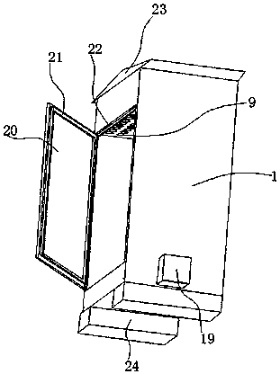
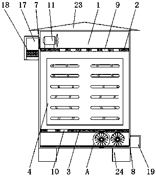
[0004] The object of the present invention is to provide a heat-dissipating power equipment box, which solves the problems of low heat dissipation efficiency and easy dust ingress in the existing power equipment box through the use of a square cylinder and dust filter.

Method used


Image

  • Heat dissipation type power equipment box
  • Heat dissipation type power equipment box
  • Heat dissipation type power equipment box

Examples


Embodiment Construction

[0028] The following will clearly and completely describe the technical solutions in the embodiments of the present invention with reference to the accompanying drawings in the embodiments of the present invention. Obviously, the described embodiments are only some, not all, embodiments of the present invention. Based on the embodiments of the present invention, all other embodiments obtained by persons of ordinary skill in the art without creative efforts fall within the protection scope of the present invention.

[0029] In describing the present invention, it is to be understood that the terms "opening", "upper", "lower", "thickness", "top", "middle", "length", "inner", "surrounding" etc. Indicating orientation or positional relationship is only for the convenience of describing the present invention and simplifying the description, and does not indicate or imply that the components or elements referred to must have a specific orientation, be constructed and operated in a sp...


PUM


Abstract

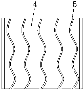
The invention discloses a heat dissipation type power equipment box, and relates to the technical field of accessories of power equipment. The heat dissipation type power equipment box comprises a boxbody; a first partition plate and a second partition plate are fixedly mounted in the box body from the top to bottom in sequence; a square cylinder is fixedly mounted on the back side of an inner cavity of the box body; bent plates are fixedly mounted between the top and the bottom of the inner cavity of the box body, and a plurality of cooling grooves are formed in the top of the square cylinder; an air inlet is formed in the left side of the box body and positioned in the first partition plate; and an air outlet is formed in the right side of the box body and positioned in the right side of the second partition plate. By setting the square cylinder and the multiple bent plates in the square cylinder, a plurality of bent channels are formed, so that the contact area between cold air andthe bent plates is relatively large, and the cooling efficiency is improved; then through the cooling grooves, the power equipment can be cooled by the cold air in an all-around manner, so that the cooling rate on the power equipment can be improved; and by adoption of the apparatus, the power equipment can be cooled efficiently and quickly, thereby facilitating safe and stable operation of the power equipment.

Description

technical field [0001] The invention belongs to the technical field of electric equipment accessories, in particular to a cooling type electric equipment box. Background technique [0002] Power equipment mainly includes power generation equipment and power supply equipment. Power generation equipment is mainly power plant boilers, steam turbines, gas turbines, water turbines, generators, transformers, etc. Power supply equipment is mainly transmission lines of various voltage levels, transformers, contactors, etc. device and so on. [0003] Some of the existing power equipment boxes have cooling equipment, and some do not. Many of the existing cooling equipment cannot meet the cooling requirements, and cannot meet the required cooling speed. The poor sealing of the power equipment box is easy to enter dust , This will cause damage to some sophisticated power equipment arcs, which is not conducive to the safe and efficient use of power. Contents of the invention [0004]...

Claims


Application Information

Patent Timeline
Patent Type & Authority Applications(China)
IPC IPC(8): H02B1/56H02B1/28H02B1/46
CPCH02B1/565H02B1/28H02B1/46
Inventor 张宝泽
Owner 张宝泽
Learn More